Cirrus Logic EP73xx User Manual
Page 22
1-8
EP7309/11/12 User’s Manual - DS508UM4
Copyright Cirrus Logic, Inc. 2003
Introduction
1
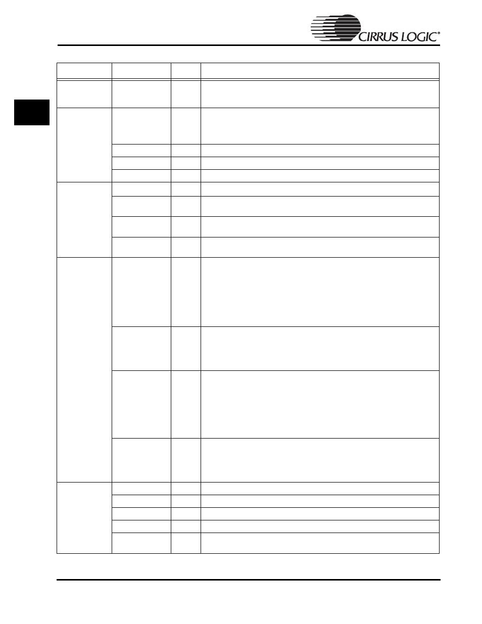
External Clock
EXPCLK
I/O
Expansion clock rate is the same as the CPU clock for 13 MHz and 18 MHz. It runs
at 36.864 MHz for 36,49 and 74 MHz modes; in 13 MHz mode this pin is used as the
clock input.
Interrupts
nMEDCHG/
nBROM
I
Media changed input; active low, deglitched. Used as a general purpose FIQ
interrupt during normal operation. It is also used on power up to configure the
processor to either boot from the internal Boot ROM, or from external memory.
When low, the chip will boot from the internal Boot ROM.
nEXTFIQ
I
External active low fast interrupt request input
EINT[3]
I
External active high interrupt request input
nEINT[1-2]
I
Two general purpose, active low interrupt inputs
Power
Management
nPWRFL
1
I
Power fail input; active low, deglitched input to force system into the Standby State
BATOK
1
I
Main battery OK input; falling edge generates a FIQ, a low level in the Standby State
inhibits system start up; deglitched input
nEXTPWR
I
External power sense; must be driven low if the system is powered by an external
source
nBATCHG
1
I
New battery sense; driven low if battery voltage falls below the "no-battery"
threshold; it is a deglitched input
State Control
nPOR
I
Power-on reset input. This signal is not deglitched. When active it completely resets
the entire system, including all the RTC registers. Upon power-up, the signal must be
held active low for a minimum of 100
µsec. after V
DD
has settled. During normal
operation, nPOR needs to be held low for at least one clock cycle of the selected
clock speed (i.e., when running at 13 MHz, the pulse width of nPOR needs to be >
77 nsec).
Note that nURESET, TEST[0], TEST[1], PE[0], PE[1], PE[2], DRIVE[0], DRIVE[1],
nMEDCHG, are all latched on the rising edge of nPOR.
RUN/CLKEN
O
This pin is programmed to either output the RUN signal or the CLKEN signal. The
CLKENSL bit is used to configure this pin. When RUN is selected, the pin will be
high when the system is active or idle, low while in the Standby State. When CLKEN
is selected, the pin will only be driven low when in the Standby State (For RUN, see
WAKEUP
1
I
Wake up is a deglitched input signal. It must also be held high for at least 125
µsec to
guarantee its detection. Once detected it forces the system into the Operating State
from the Standby State. It is only active when the system is in the Standby State.
This pin is ignored when the system is in the Idle or Operating State. It is used to
wakeup the system after first power-up, or after software has forced the system into
the Standby State. WAKEUP will be ignored for up to two seconds after nPOR goes
HIGH. Therefore, the external WAKEUP logic must be designed to allow it to rise and
stay HIGH for at least 125 usec, two seconds after nPOR goes HIGH.
nURESET
1
I
User reset input; active low deglitched input from user reset button.
This pin is also latched upon the rising edge of nPOR and read along with the input
pins nTEST[0-1] to force the device into special test modes. nURESET does not
reset the RTC.
DAI, CODEC or
SSI2 Interface
for pin
assignment and
direction following
multiplexing)
SSICLK
I/O
DAI/CODEC/SSI2 clock signal
SSITXFR
I/O
DAI/CODEC/SSI2 serial data output frame/synchronization pulse output
SSITXDA
O
DAI/CODEC/SSI2 serial data output
SSIRXDA
I
DAI/CODEC/SSI2 serial data input
SSIRXFR
I/O
SSI2 serial data input frame/synchronization pulse
DAI/CODEC external clock input
Table 1-4: External Signal Functions (Continued)
Function
Signal Name
Signal
Description