System flag register 1 (sysflg1), System flag register 1 (sysflg1) -9, Table 5-4: arm720t clock speed settings -9 – Cirrus Logic EP73xx User Manual
Page 69
EP7309/11/12 User’s Manual - DS508UM4
5-9
Copyright Cirrus Logic, Inc. 2003
System Registers
55
5
Refer to the Expansion Bus Controller chapter for explicit details
on programmed wait states at different bus frequencies.
DAISEL:
When set, selects the DAI interface. When cleared, selects the SSI
interface.
ADCCKNSEN:When set, ADC configuration data is transmitted on
ADCOUT
at the rising edge of the
ADCCLK
, and data is read back on the
falling edge of the
ADCIN
pin. When clear, the opposite edges are
used.
VERSN:
These read-only bits will always read ‘000’ on the EP73xx.
Reserved-0:This bit must always be set to zero.
128Fs:
DAI Frame size select. When set, the DAI will operate on 128-bit
frames. When cleared, the DAI uses 64-bit frames.
ENPD67:
Port D bits 6 and 7 enable. When this bit is set, these bits on Port D
are enabled as GPIOs. When cleared, the pins assigned
PD[6]
and
PD[7]
are used as
SDQM[0]
and
SDQM[1]
respectively for the
SDRAM interface. ENPD67 must be clear in order to properly use
the SDRAM interface.
System Flag Register 1 (SYSFLG1)
Address:
0x8000.0140, Read Only
Definition:
The SYSFLG1 system flag register is a 32-bit read only register. It
provides information regarding the status of the CPU and associated
peripherals.
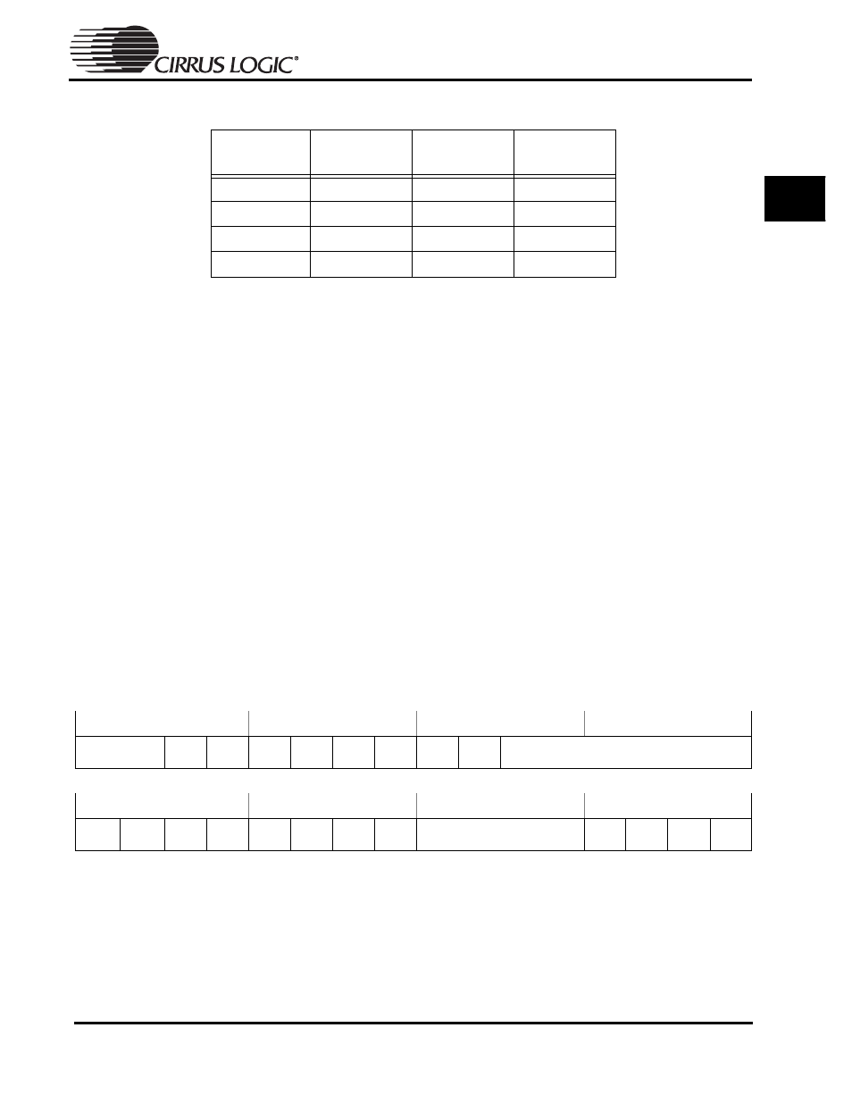
Table 5-4: ARM720T Clock Speed Settings
CLKCTL[1-0]
Value
Processor
Frequency
Memory Bus
Frequency
Wait State
Scaling
00
18.432 MHz
18.432 MHz
1
01
36.864 MHz
36.864 MHz
2
10
49.152 MHz
36.864 MHz 2
11
73.728 MHz
36.864 MHz
2
31
30
29
28
27
26
25
24
23
22
21
20
19
18
17
16
VERID
ID
BOOTBI
T1
BOOTBI
T0
SSIBUS
Y
CTXFF
CRXFE
UTXFF1
URXFE1
RTCDIV
15
14
13
12
11
10
9
8
7
6
5
4
3
2
1
0
CLDFLG
PFFLG
RSTFLG
NBFLG
UBUSY
1
DCD
DSR
CTS
DID
WUON
WUDR
DCDET
MCDR