Dai interface, Dai interface -4 – Cirrus Logic EP73xx User Manual
Page 128
16-4
EP7309/11/12 User’s Manual - DS508UM4
Copyright Cirrus Logic, Inc. 2003
DAI/CODEC/SSI2
16
DAI Interface
The DAI (Digital Audio Interface) is the buffering and synchronization mechanism
for sending decoded digital music frames to the external CODEC(s) to be converted
into audio. The DAI provides three synchronization clocks that sync the data, frame
by frame, for the external ADC and DAC devices. Both 128 bit and 64 bit frame sizes
are supported. All but 32 bits out of the entire frame are padded with ‘0’, allowing the
EP73xx to support two channels with a maximum sample width of 16 bits each.
Two eight-sample-deep transmit FIFOs and two twelve-sample-deep receive FIFOs
precede the output and input shift registers. When a FIFO is half-empty or half-full
(respectively), an interrupt (FIQ) is generated. An interrupt handler may be used to
automatically load or unload samples from the FIFOs with minimal CPU
intervention.
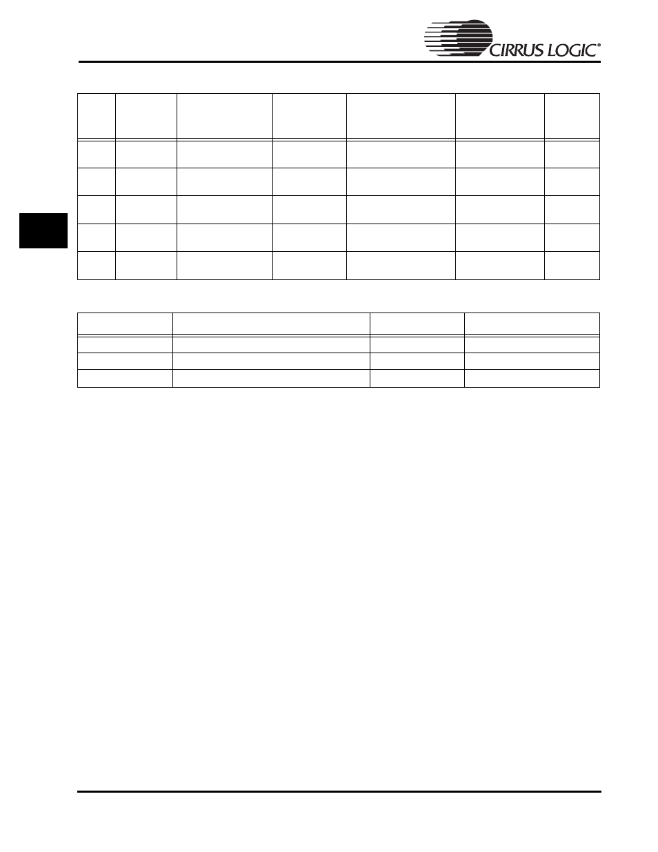
Table 16-3: Pin Sharing for Multiplexor
Pin
No.
LQFP
External
Pin Name
SSI2
Slave Mode
(Internal Name)
SSI2
Master Mode
CODEC
Internal Name
DAI
Internal Name
Strength
63
SSICLK
SSICLK = serial bit
clock; Input
Output
PCMCLK =
Output
SCLK =
Output
1
65
SSITXFR
SSKTXFR = TX frame
sync; Input
Output
PCMSYNC = Output
LRCK = Output
1
66
SSITXDA
SSITXDA = TX data;
Output
Output
PCMOUT = Output
SDOUT = Output
1
67
SSIRXDA
SSIRXDA = RX data;
Input
Input
PCMIN = Input
SDIN = Input
68
SSIRXFR
SSIRXFR = RX frame
sync; Input
Input
p/u
(use a 10k pull-up)
MCLK
1
Table 16-4: Communication Interface Performance
Type
Comments
Referred To As
Max. Transfer Speed
SPI/Microwire 2
Master/slave mode
SSI2 Interface
512 kbits/s
DAI Interface
CD quality DACs and ADCs
DAI Interface
1.536 Mbits/s
CODEC Interface
Only for use in the PLL clock mode
CODEC Interface
64 kbits/s