Festo Контроллеры двигателя SFC-LAC User Manual
Page 57
3. Installation
3−7
Festo P.BE−GDCP−SFC−LACI−PB−E N en 0812NH
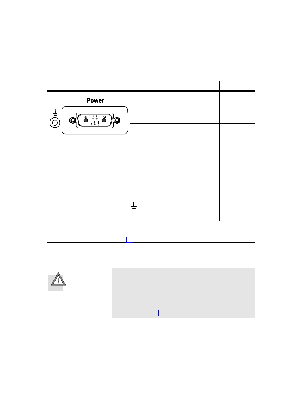
Connection
Pin
Designation
Function
Colour
1)
A1
Load voltage
+48 VDC load
Black, 1
A2
Load voltage
GND load
Black, 2
1
Logic voltage
+24 VDC logic
White
2
Logic voltage
GND logic
Brown
3
Hardware
enable
+24 VDC
hardware enable
Green
4
FE
FE
3)
ć
2)
5
Hardware
enable
GND hardware
enable
yellow
ć
Plug housing
FE
3)
Earthing strap
with cable lug
M4
Earth
terminal
(housing)
FE
3)
ć
1)
Wire colours of supply cable KPWR−MC−1−SUB−15HC−...
2)
With cable type KPWR−MC−1−SUB−15HC−... not connected.Ă
3)
Use only one connection; see section 3.3
Tab. 3/3:
Power" connection (voltage supply) on the SFC−LACI
Caution
Damage to the device
The power supply inputs on the SFC−LACI have no special
protection against overvoltage.
·
Make sure the permissible voltage tolerance is never
exceeded; see Tab. 3/4.
- Круглые цилиндры DSNUP (64 pages)
- Линейные приводы DGPL, метрические (2 pages)
- Линейные приводы DGPL, метрические (2 pages)
- Цилиндры с зажимным модулем DNCKE (100 pages)
- Линейные приводы DGPL, метрические (6 pages)
- Приводы винт-гайка EGC-HD-BS (2 pages)
- Привод со шпинделем EGC-BS (2 pages)
- Пневматические линейные приводы DGC (2 pages)
- Пневматические линейные приводы DGC (2 pages)
- Пневматические линейные приводы DGC (2 pages)
- Пневматические линейные приводы DGC (2 pages)
- Линейные приводы DGPL, метрические (40 pages)
- Шаговые моторы MTRE-ST (140 pages)
- Линейные приводы DGPL, метрические (2 pages)
- Ременные приводы ELGA-TB-G (2 pages)
- Промежуточная позиция для линейного модуля SLG (88 pages)
- Пассивные нправляющиеFDG-ZR-RF (76 pages)
- Пневматические линейные приводы SLG (100 pages)
- Монтажные элементы для датчиков положения (2 pages)
- Линейные приводы DGO, метрические (88 pages)
- Линейные модули HMP (76 pages)
- Линейные модули HMP (12 pages)
- Линейные модули HMP (56 pages)
- Линейные модули HMP (2 pages)
- Cтопорный цилиндр DFST (76 pages)
- Линейно-поворотный зажим CLR (100 pages)
- Пневматический мускул DMSP (80 pages)
- Устройство подачи BV (4 pages)
- Линейный привод с датчиком перемещения DFPI (4 pages)
- Линейный привод с датчиком перемещения DFPI (5 pages)
- Неполноповоротные приводы Sypar DAPS (5 pages)
- Неполноповоротный привод DFPB (18 pages)
- Амортизаторы YSRWJ (64 pages)
- Направляющая FDG (64 pages)
- Поворотные модули DSM (12 pages)
- Линейные приводы DGPL, метрические (112 pages)
- Электроцилиндр (134 pages)
- Электроцилиндр ESBF (72 pages)
- Линейный привод ELGL-LAS (216 pages)
- Серводвигатели EMMS-AS-100-S (6 pages)
- Электромотор MTR-DCI (182 pages)
- Электромотор MTR-DCI (352 pages)
- Электромотор MTR-DCI (316 pages)
- Электромотор MTR-DCI (306 pages)
- Контроллеры двигателя CMMS-ST (136 pages)