Festo Контроллеры двигателя SFC-LAC User Manual
Page 54
3. Installation
3−4
Festo P.BE−GDCP−SFC−LACI−PB−E N en 0812NH
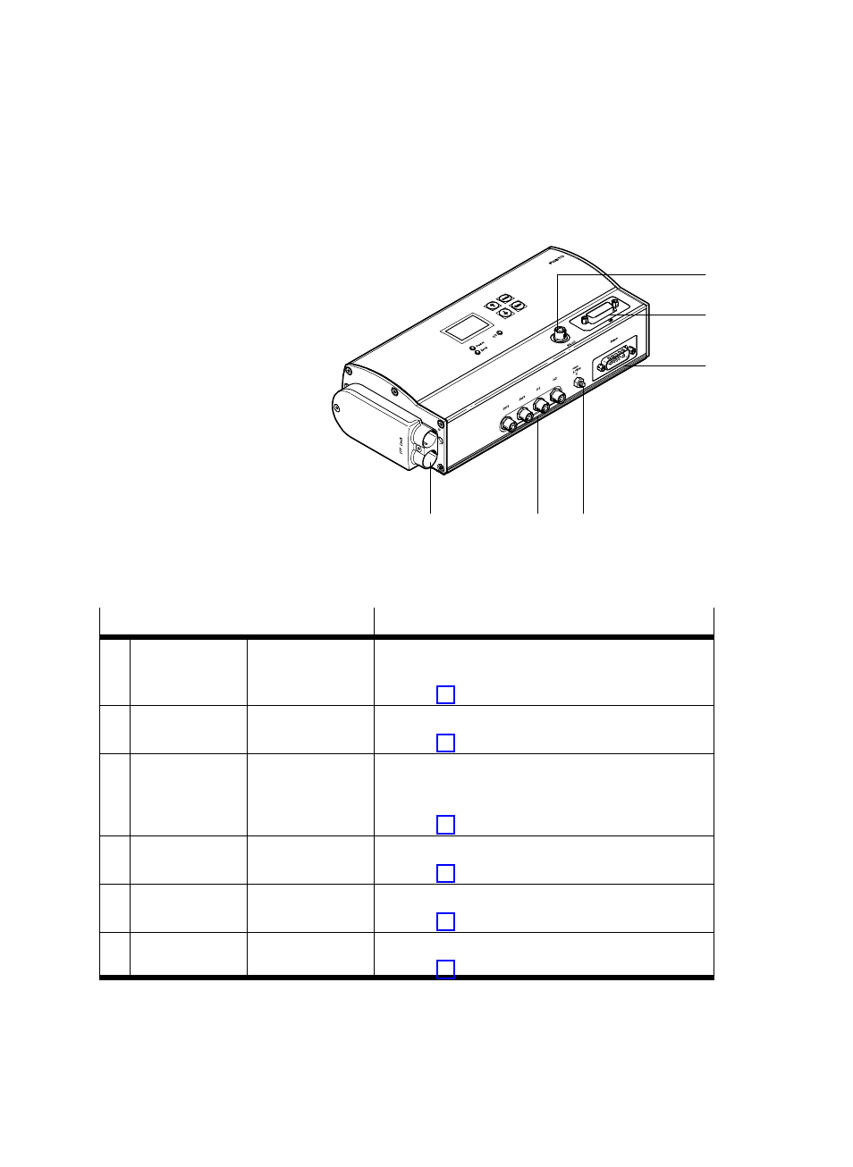
1
Parameterising
interface (RS232)
2
Controller interface
3
Voltage supply
4
Earth terminal
5
Local digital I/Os
6
Motor connection
(e.g.ĂDNCE−...−LAS)
1
2
3
4
5
6
Fig. 3/1:
Connections to the SFC−LACI
Connection to the SFC−LACI−PB
Description
1
Parameterising
interface
M8 socket, 4−pin
RS232 interface for parameterising, commissioning
and diagnosis via FCT
} section 3.5
2
Controller
interface
Sub−D, 9−pin,
socket
Interface for connecting to a PLC controller
} section 3.6
3
Voltage supply
Sub−D plug, 7WT
Voltage connection with 2 high−current contacts and
5 low−current contacts (separate load and logic
voltage supply)
} section 3.2
4
Earth terminal
Stud bolt, M4
Connection for functional earth
} section 3.3
5
Local digital I/Os
M8 socket, 3−pin
Local digital inputs and outputs
} section 3.9
6
Motor terminal
Plug connector,
typeĂITT Cm3
Power supply for linear motor and sensor signals
} section 3.4
Tab. 3/1:
Overview of connections
- Круглые цилиндры DSNUP (64 pages)
- Линейные приводы DGPL, метрические (2 pages)
- Линейные приводы DGPL, метрические (2 pages)
- Цилиндры с зажимным модулем DNCKE (100 pages)
- Линейные приводы DGPL, метрические (6 pages)
- Приводы винт-гайка EGC-HD-BS (2 pages)
- Привод со шпинделем EGC-BS (2 pages)
- Пневматические линейные приводы DGC (2 pages)
- Пневматические линейные приводы DGC (2 pages)
- Пневматические линейные приводы DGC (2 pages)
- Пневматические линейные приводы DGC (2 pages)
- Линейные приводы DGPL, метрические (40 pages)
- Шаговые моторы MTRE-ST (140 pages)
- Линейные приводы DGPL, метрические (2 pages)
- Ременные приводы ELGA-TB-G (2 pages)
- Промежуточная позиция для линейного модуля SLG (88 pages)
- Пассивные нправляющиеFDG-ZR-RF (76 pages)
- Пневматические линейные приводы SLG (100 pages)
- Монтажные элементы для датчиков положения (2 pages)
- Линейные приводы DGO, метрические (88 pages)
- Линейные модули HMP (76 pages)
- Линейные модули HMP (12 pages)
- Линейные модули HMP (56 pages)
- Линейные модули HMP (2 pages)
- Cтопорный цилиндр DFST (76 pages)
- Линейно-поворотный зажим CLR (100 pages)
- Пневматический мускул DMSP (80 pages)
- Устройство подачи BV (4 pages)
- Линейный привод с датчиком перемещения DFPI (4 pages)
- Линейный привод с датчиком перемещения DFPI (5 pages)
- Неполноповоротные приводы Sypar DAPS (5 pages)
- Неполноповоротный привод DFPB (18 pages)
- Амортизаторы YSRWJ (64 pages)
- Направляющая FDG (64 pages)
- Поворотные модули DSM (12 pages)
- Линейные приводы DGPL, метрические (112 pages)
- Электроцилиндр (134 pages)
- Электроцилиндр ESBF (72 pages)
- Линейный привод ELGL-LAS (216 pages)
- Серводвигатели EMMS-AS-100-S (6 pages)
- Электромотор MTR-DCI (182 pages)
- Электромотор MTR-DCI (352 pages)
- Электромотор MTR-DCI (316 pages)
- Электромотор MTR-DCI (306 pages)
- Контроллеры двигателя CMMS-ST (136 pages)