Festo Контроллеры двигателя SFC-LAC User Manual
Page 224
B. Supplementary information
B−4
Festo P.BE−GDCP−SFC−LACI−PB−E N en 0812NH
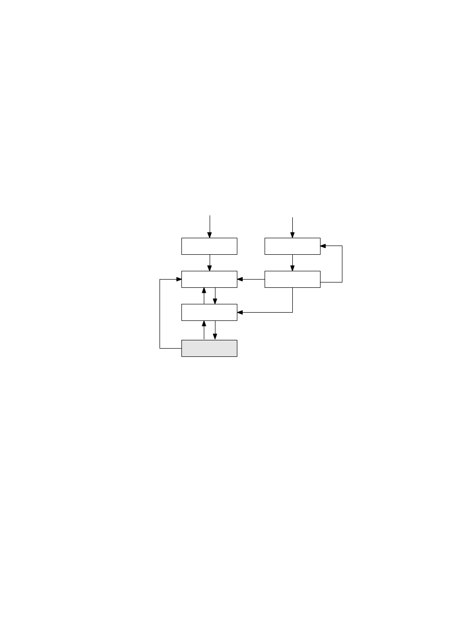
Notes on representing the finite status machine
The transition T3 changes to state S4, which itself contains its
own sub−state machine, the states of which are marked with
SAx" and the transitions of that are marked with TAx". This
enables an equivalent circuit diagram to be used, in which the
internal states SAx are omitted:
Switched off
S1
Controller
switched on
S4
Drive enabled
S2 Drive locked
S5
Reaction
to fault
S6
Malfunction
From all statuses
Operation
enabled
T6
T2
T5
T3
T4
T1
T7*
T8
T10
T9
S5
T11
S4
Fig. B/2: Finite state machine equivalent circuit diagram
Transitions T4, T6 and T7* are executed from every sub−state
SAx and automatically have a higher priority than any transiĆ
tion TAx. Such a structure is a simplification. It is not thereĆ
fore necessary to define out of each SAx state a separate
transition as per S3 for the reaction to Stop (S3: drive held
stationary).
Reaction to faults
T7 (Fault recognised") has the highest priority and receives
the asterisk ā*ā".
T7 is then derived from S5 and S6 when an error of higher
priority occurs. As a result, a slight error can displace a
serious error.