Product-specific terms and abbreviations, Product−specific terms and abbreviations – Festo Контроллеры двигателя SFC-LAC User Manual
Page 18
Contents and general instructions
XVI
Festo P.BE−GDCP−SFC−LACI−PB−E N en 0812NH
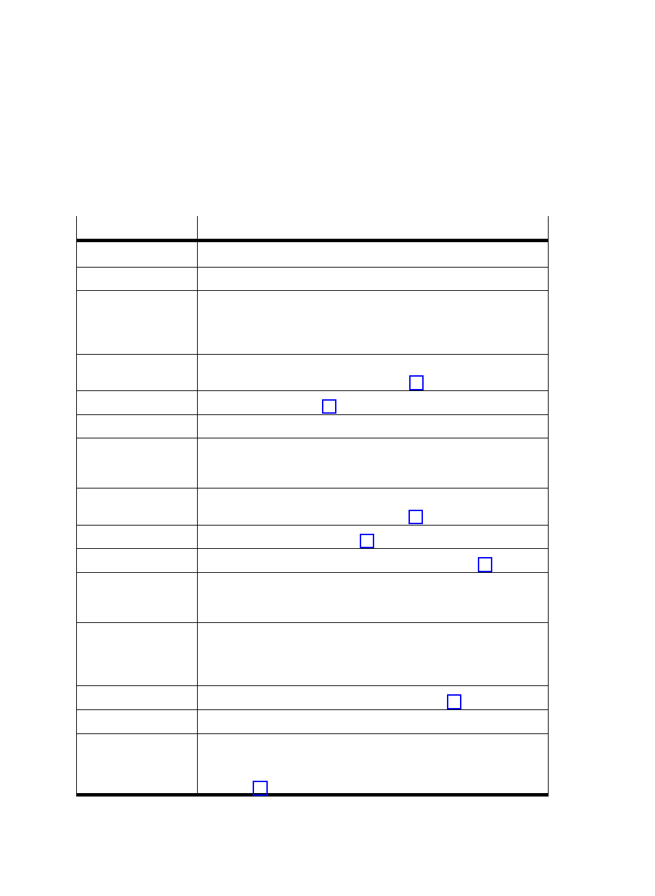
Product−specific terms and abbreviations
Term / abbreviation
Meaning
0−Signal
0 V present at input or output (positive logic, corresponds to LOW)
1−Signal
24 V present at input or output (positive logic, corresponds to HIGH)
Acknowledge
Confirm, reply message, e.g.ĂAcknowledge START".
Acknowledge a fault". The user confirms that he has noted the fault.
The device then leaves the fault status (if the fault still exists, it will be
displayed again).
Applied load
(Additional load)
The mass of a workpiece.
Applies only to a single positioning record, seeĂFig. 0/1.
AZ (= axis zero point),
Axis zero point; see section 1.1.5
EMC
Electromagnetic compatibility
FCT (= Festo
Configuration Tool)
Software with uniform project and data management for all supported
device types. The special requirements of a device type are supported
with the necessary descriptions and dialogues by means of PlugIns.
FHPP
Festo Handling and Positioning Profile": Uniform fieldbus data profile for
positioning controllers from Festo; see section 1.2.2
FHPP standard
FHPP sequence control, see section 1.2.2
FPC
Festo Parameter Channel" for parameter access; see section 1.2.2
HALT
With a HALT signal a running positioning movement is interrupted and the
drive stops. The positioning record remains active, i.e.Ăwith a new START
signal the record will be continued. Compare STOP.
HMI
Human Machine Interface" refers to the control panel on the variant
SFC−LACI−...−H2. [HMI = on] means that parameterisation and operation
can begin using the control panel or FCT. The control interface is then
deactivated.
Homing
See overview of measuring reference system in section 1.1.5
I/O
Input and/or output
Load voltage
Logic voltage
The load voltage supplies the power electronics of the motor controller
and thereby the motor. The logic voltage supplies the evaluation and
control logic of the motor controller as well as the local digital I/Os
(seeĂsection 3.2).