Allied Telesis AT-8550 User Manual
Page 99
AT-9108, AT-8518, AT-8525, and AT-8550 User’s Guide
6-5
When the switches in this configuration start up, STP configures each
STPD such that there are no active loops in the topology. STP could
configure the topology in a number of ways to make it loop-free.
, the connection between Switch A and Switch B is put
into blocking state, and the connection between Switch Y and
Switch Z is put into blocking state. After STP converges, all the VLANs
can communicate, and all bridging loops are prevented.
The VLAN Marketing, which has not been assigned to either STPD1 or
STPD2, communicates using all five switches. The topology has no
loops, because STP has already blocked the port connection
between Switch A and Switch B, and between Switch Y and Switch Z.
Within a single STPD, you must be extra careful when configuring
your VLANs.
illustrates a network that has been incorrectly
set up using a single STPD so that the STP configuration disables the
ability of the switches to forward VLAN traffic.
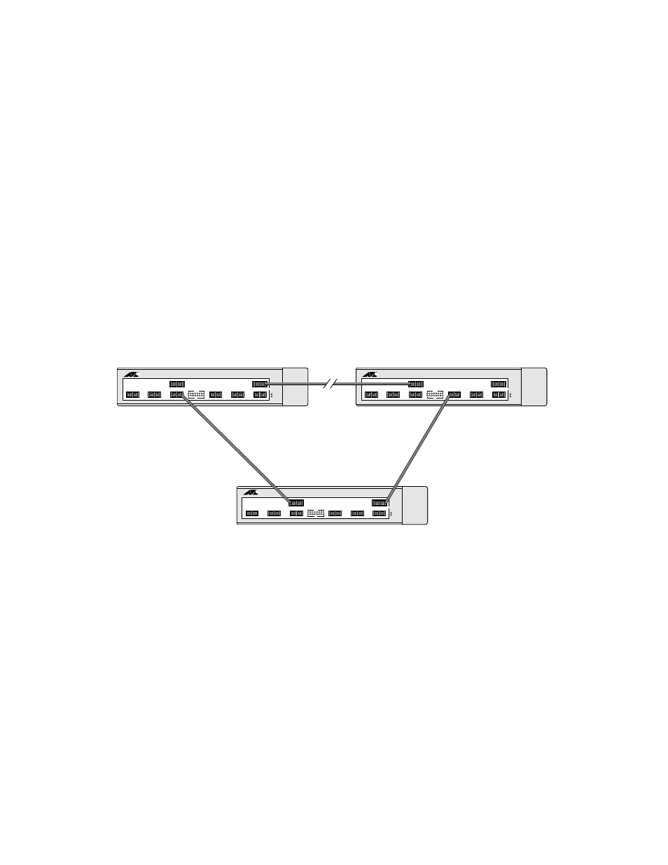
Figure 6-2 Tag-Based STP Configuration
The tag-based network in
has the following configuration:
❑ Switch 1 contains VLAN Marketing and VLAN Sales.
❑ Switch 2 contains VLAN Engineering and VLAN Sales.
❑ Switch 3 contains VLAN Marketing, VLAN Engineering, and
VLAN Sales.
❑ The tagged trunk connections for three switches form a
triangular loop that is not permitted in an STP topology.
❑ All VLANs in each switch are members of the same STPD.
Marketing & Sales
Marketing, Sales & Engineering
Sales & Engineering
Switch 1
Switch 3
Switch 2
CentreCOM
CentreCOM
CentreCOM