4 pulse measurement problems, 1 pay attention to specifications, 2 input filters and signal attenuation – Campbell Scientific CR800 and CR850 Measurement and Control Systems User Manual
Page 305: Figure 92: pulse-sensor output signal types, Figure 93: switch-closure pulse sensor
Section 8. Operation
305
frequency is not varying over the execution interval. The calculation returns the
average regardless of how the signal is changing.
8.1.5.4 Pulse Measurement Problems
8.1.5.4.1 Pay Attention to Specifications
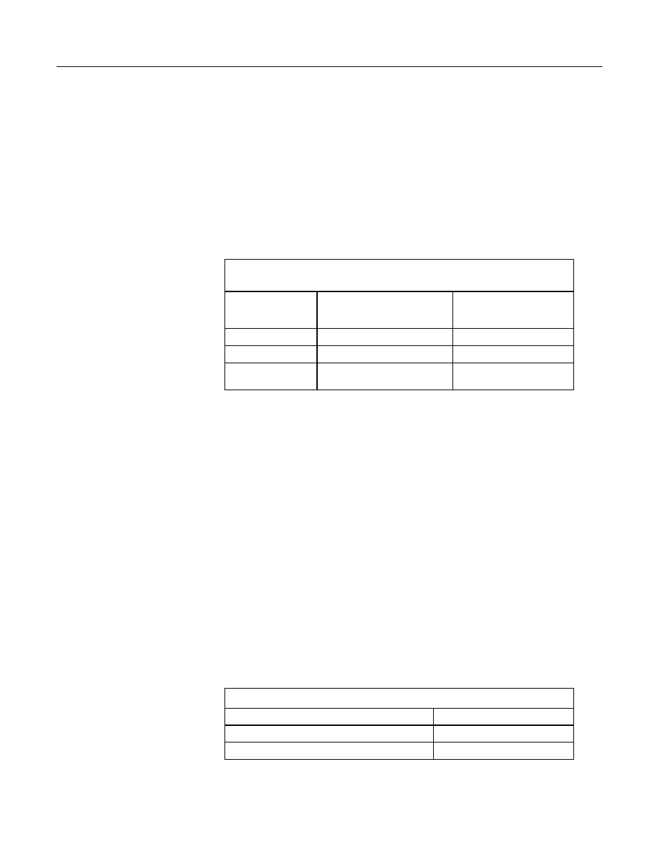
The table Example of Differing Specifications for Pulse Input Channels
(p. 305)
compares specifications for pulse-input channels to emphasize the need for
matching the proper device to application. Take time to understand signals to be
measured and compatible channels.
Table 67. Example of Differing Specifications for Pulse-Input
Channels
Pulse Channels
P1, P2
Digital I/O Channels
C1, C2, C3, C4,
C5, C6, C7, C8
High Frequency Max
250 kHz
400 kHz
Max Input Voltage
20 Vdc
16 Vdc
State Transition
Thresholds
Count upon transition from
<0.9 to >2.2 Vdc
Count upon transition from
<1.2 to >3.8 Vdc
8.1.5.4.2 Input Filters and Signal Attenuation
Pulse-input channels are equipped with input filters to reduce spurious noise that
can cause false counts. The higher the time constant (τ) of the filter, the tighter
the filter. Table Time Constants
(p. 305)
lists τ values for pulse-input channels. So,
while TimerIO() frequency measurement may be superior for clean signals, a
pulse channel filter (much higher τ) may be required to get a measurement on a
dirty signal.
Input filters, however, attenuate the amplitude (voltage) of the signal. The
amount of attenuation is a function of the frequency passing through the filter.
Higher-frequency signals are attenuated more. If a signal is attenuated enough, it
may not pass the state transition thresholds required by the detection device (listed
in table Pulse-Input Channels and Measurements
(p. 39)
). To avoid over
attenuation, sensor output voltage must be increased at higher frequencies. As an
example, table Filter Attenuation of Frequency Signals
(p. 306)
lists low-level ac
frequencies and the voltages required to overcome filter attenuation.
For pulse-input channels P1 – P2, an RC input filter with an approximate 1-
μs
time constant precedes the inverting CMOS input buffer. The resulting amplitude
reduction is illustrated in figure Amplitude Reduction of Pulse-Count Waveform
(p.
For a 0- to 5-Vdc square wave applied to a pulse channel, the maximum
frequency that can be counted in high-frequency mode is approximately 250 kHz.
Table 68. Time Constants (τ)
Measurement
τ
Pulse channel, high-frequency mode
1.2
Pulse channel, switch-closure mode
3300