1 input limits, Figure 83: running-average frequency response – Campbell Scientific CR800 and CR850 Measurement and Control Systems User Manual
Page 271
Section 8. Operation
271
instructions BrFull(), BrFull6W(), BrHalf4W(), TCDiff(), and VoltDiff ()
instructions perform DIFF voltage measurements.
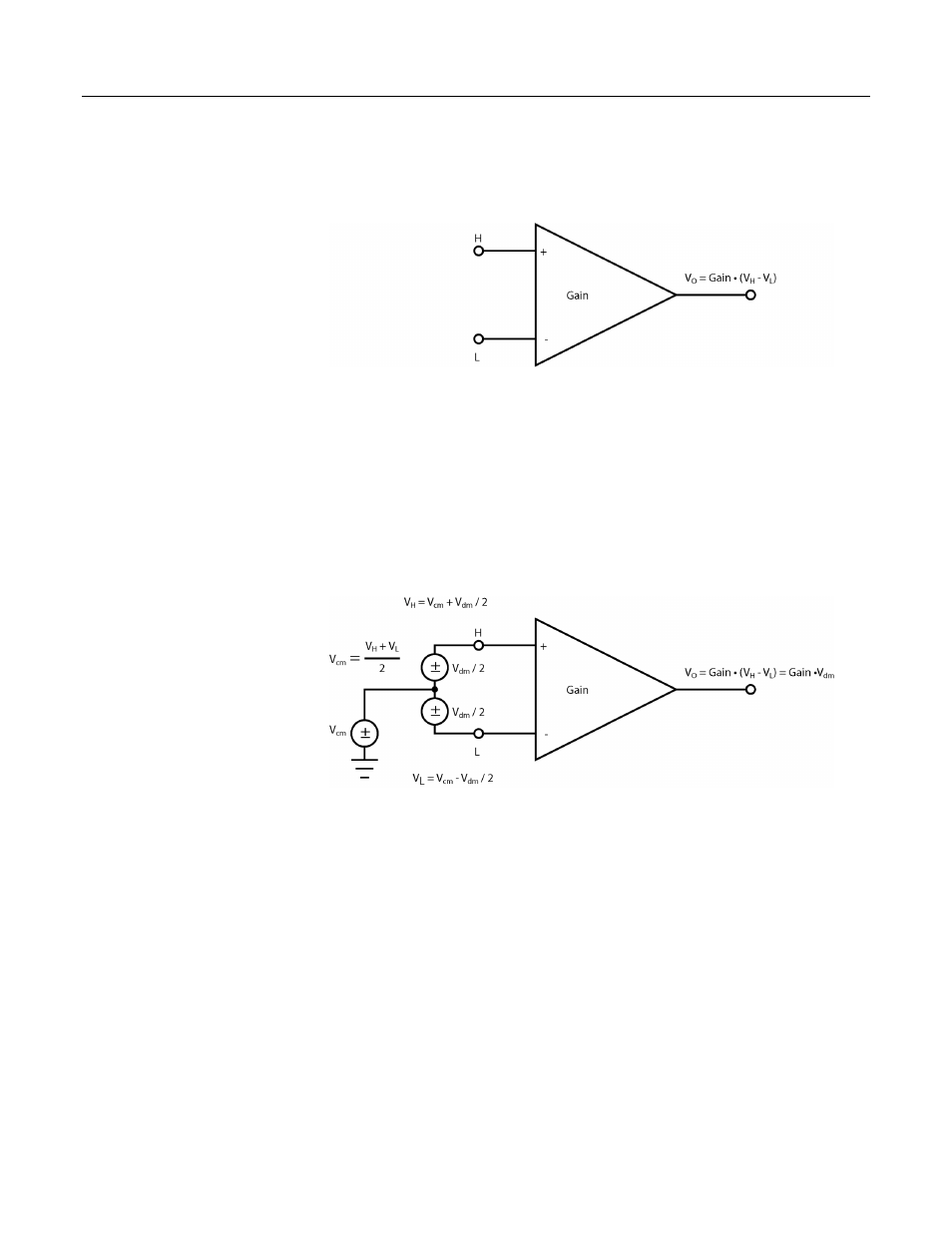
Figure 85: PGI amplifier
A PGIA processes the difference between the H and L inputs, while rejecting
voltages that are common to both inputs. Figure PGIA with Input Signal
Decomposition
(p. 271),
illustrates the PGIA with the input signal decomposed into a
common-mode voltage (V
cm
) and a DIFF-mode voltage (V
dm
). The common-mode
voltage is the average of the voltages on the V
H
and V
L
inputs, i.e., V
cm
= (V
H
+
V
L
)/2, which can be viewed as the voltage remaining on the H and L inputs with
the DIFF voltage (V
dm
) equal to 0. The total voltage on the H and L inputs is
given as V
H
= V
cm
+ V
dm
/2, and V
L
= V
cm
– V
dm
/2, respectively.
Figure 86: PGIA with input signal decomposition
8.1.2.1 Input Limits
The input limits specification is the voltage range, relative to CR800 ground,
which both H and L input voltages must be within to be processed correctly by the
PGIA. Input limits for the CR800 are ±5 Vdc. Input voltages in which V
H
or V
L
are beyond the ±5 Vdc input limits may suffer from undetected measurement
errors. The term “common-mode range”, which defines the valid range of
common-mode voltages, is often used instead of “input limits.” For DIFF voltages
that are small compared to the input limits, common-mode range is essentially
equivalent to input limits. Yet from figure PGIA with Input Signal Decomposition
(p. 271),
Common‐Mode Range = ± 5 Vdc – | V
dm
/2 |,
indicating a reduction in common-mode range for increasing DIFF signal
amplitudes. For example, with a 5000 mV DIFF signal, the common-mode range