1 minimizing settling errors, 2 measuring the necessary settling time – Campbell Scientific CR800 and CR850 Measurement and Control Systems User Manual
Page 283
Section 8. Operation
283
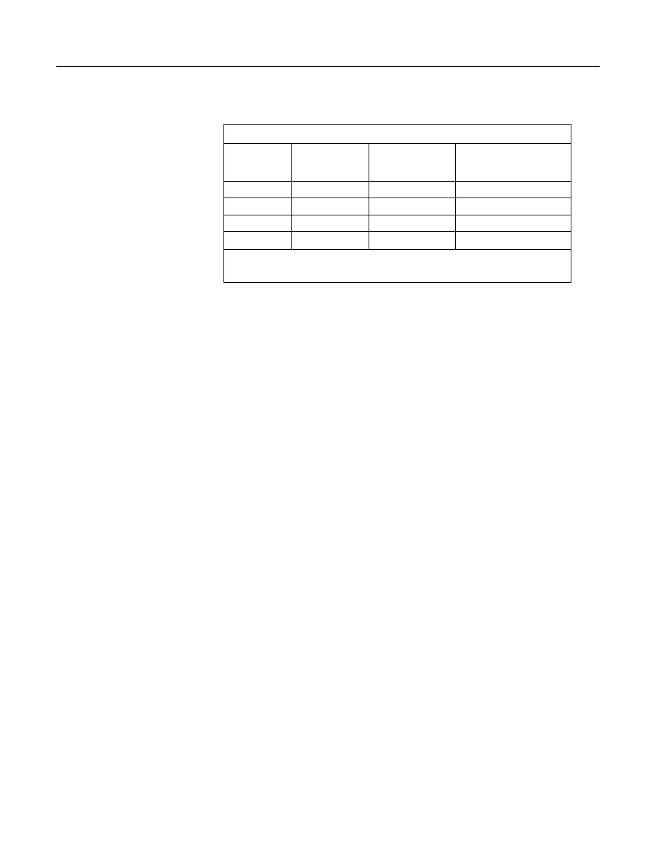
Table 57. CRBasic Measurement Settling Times
Settling
Time
Entry
Input
Voltage
Range
Integration
Code
Settling
Time
1
0 All
250
450 µs (default)
0 All
_50Hz
3 ms (default)
0 All
_60Hz
3 ms (default)
>100 All
X
2
μs entered
1
Minimum settling time required to allow the input to settle to CR800 resolution specifications.
2
X is an integer >100.
A settling time is required for voltage measurements to minimize the effects of the
following sources of error:
• A small switching transient occurs when the CR800 switches to the single-
ended or differential channel to be measured.
• A relatively large transient may be induced on the signal conductor via
capacitive coupling during a bridge measurement from an adjacent excitation
conductor.
• 50-Hz or 60-Hz integrations require a relatively long reset time of the internal
integration capacitor before the next measurement due to dielectric
absorption.
8.1.2.8.1 Minimizing Settling Errors
When long lead lengths are required the following general practices can be used
to minimize or measure settling errors:
• Do not use wire with PVC-insulated conductors. PVC has a high dielectric,
which extends input settling time.
• Where possible, run excitation leads and signal leads in separate shields to
minimize transients.
• When measurement speed is not a prime consideration, additional time can be
used to ensure ample settling time. The settling time required can be
measured with the CR800.
•
8.1.2.8.2 Measuring the Necessary Settling Time
Settling time for a particular sensor and cable can be measured with the CR800.
Programming a series of measurements with increasing settling times will yield
data that indicate at what settling time a further increase results in negligible
change in the measured voltage. The programmed settling time at this point
indicates the true settling time for the sensor and cable combination.
CRBasic example Measuring Settling Time
(p. 284)
presents CRBasic code to help
determine settling time for a pressure transducer utilizing a high-capacitance
semi-conductor. The code consists of a series of full-bridge measurements
(BrFull()) with increasing settling times. The pressure transducer is placed in