Horner APG XLt OCS User Manual
Page 76
CH. 14 MAN0878-04-EN
August 12, 2009
Page 76 of 100
ECN # 979
The Output State On Controller Stop group box contains items to allow the user to specify how the
remaining digital outputs behave when the controller is stopped. These items can either hold their value
or default to some value when the controller is stopped.
14.8
Analog Input Configuration
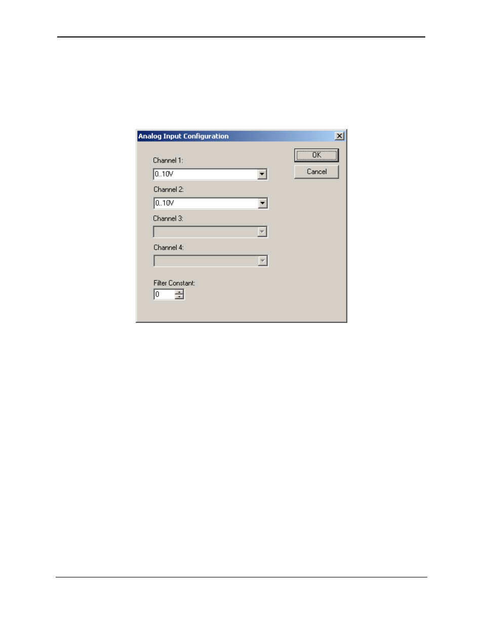
The following figure illustrates the Analog Input Configuration dialog.
Figure 14-3 – Analog Input Configuration Dialog
The Channel x drop down windows allow the user to specify the mode for each analog input to operate.
The Channel x drop down windows are enabled/disabled according to which model is being configured.
All of the models have the following modes available:
- 0..10V
- 0..20mA
- 4..20mA
On model 005, channels 3 and 4 also have the following modes available:
- 100mV
-
PT100 DIN RTD, 1/20
°c
-
Type J Thermocouple, 1/20
°c
-
Type K Thermocouple, 1/20
°c
-
Type N Thermocouple, 1/20
°c
-
Type T Thermocouple, 1/20
°c
-
Type E Thermocouple, 1/20
°c
-
Type R Thermocouple, 1/20
°c
-
Type S Thermocouple, 1/20
°c
-
Type B Thermocouple, 1/20
°c
The Filter Constant provides filtering to all channels.