Horner APG XLt OCS User Manual
Page 75
MAN0878-04-EN CH. 14
August 12, 2009
Page 75 of 100
ECN # 979
14.7
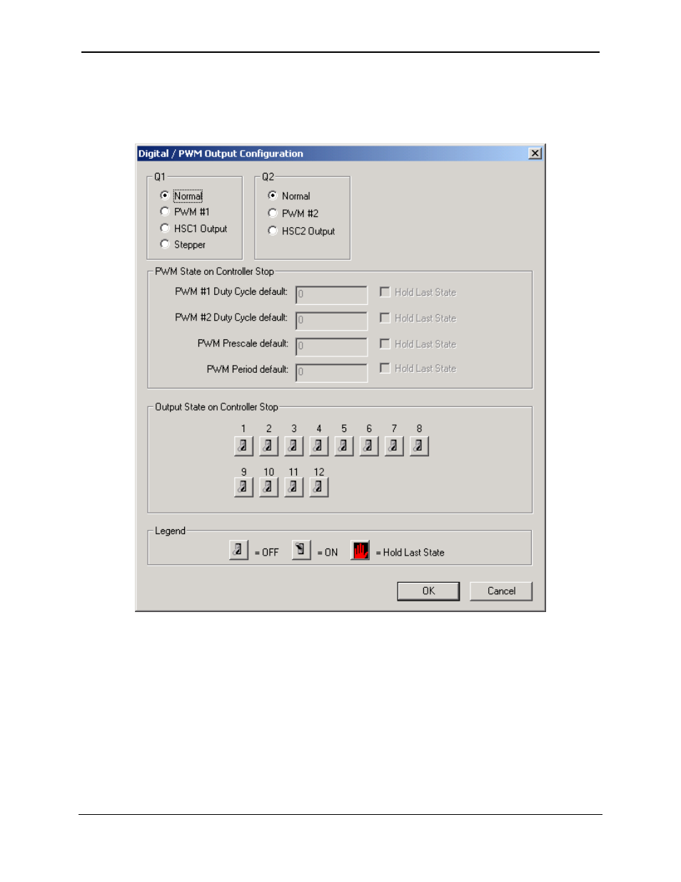
Digital Output / PWM Configuration
The following figure illustrates the Digital Output / PWM Configuration dialog.
Figure 14-2 – Digital Output / PWM Configuration Dialog
The Q1 and Q2 group boxes allow the user to specify the operation of the multi-function outputs.
The PWM State On Controller Stop group box contains items that allow the user to specify how the
PWM outputs behave when the controller is stopped. These items can either hold their value or default to
some value when the controller is stopped.
Note that the PWM outputs are set to the OFF state at power-up and during program download
and remain in that state until the unit is placed in RUN
This manual is related to the following products: