Horner APG XLt OCS User Manual
Page 18
CH. 3 MAN0878-04-EN
August 12, 2009
Page 18 of 100
ECN # 979
3.6
Factors Affecting Panel Layout Design and Clearances
The designer of a panel layout needs to assess the requirements of a particular system and to consider
the following design factors. A convenient checklist is provided on page 19.
3.6.1
Clearance / Adequate Space
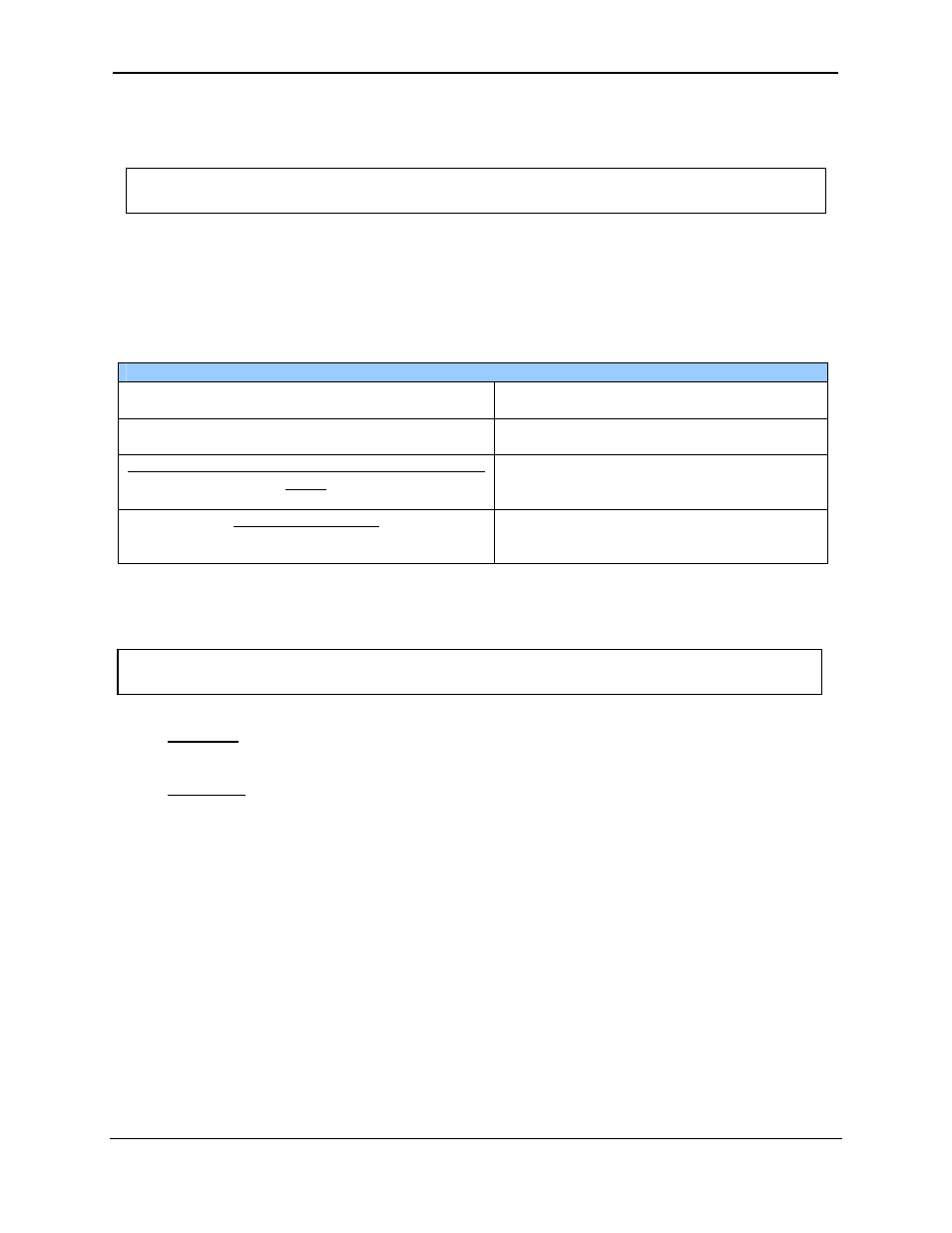
Install devices to allow sufficient clearance to open and close the panel door.
Table 3.1 – Minimum Clearance Requirements for Panel Box and Door
Minimum Distance between base of device and
sides of cabinet
2 inches (50.80mm)
Minimum Distance between base of device and
wiring ducts
1.5 inches (38.10mm)
If more than one device installed in panel box (or on
door):
Minimum Distance between bases of each device
4 inches between bases of each device
(101.60mm)
When door is closed:
Minimum distance between device and closed door
(Be sure to allow enough depth for XLe/XLt.)
2 inches (50.80mm)
3.6.2 Grounding
Panel box: The panel box needs to be properly connected to earth ground to provide a good
common ground reference.
Panel door: Tie a low impedance ground strap between the panel box and the panel door to
ensure that they have the same ground reference.
3.6.3 Temperature
/
Ventilation
Ensure that the panel layout design allows for adequate ventilation and maintains the specified
ambient temperature range. Consider the impact on the design of the panel layout if operating at
the extreme ends of the ambient temperature range. For example, if it is determined that a
cooling device is required, allow adequate space and clearances for the device in the panel box
or on the panel door.
Warning: It is important to follow the requirements of the panel manufacturer and to follow
all applicable electrical codes and standards.
Warning: Be sure to meet the ground requirements of the panel manufacturer and also meet
applicable electrical codes and standards.