Chapter 5 : serial communications, Chapter 5: serial communications – Horner APG XLt OCS User Manual
Page 23
MAN0878-04-EN CH. 5
August 12, 2009
Page 23 of 100
ECN # 979
CHAPTER 5: SERIAL COMMUNICATIONS
5.1 Overview
All XLe/XLt models provide two serial ports, which are implemented with 8-pin modular RJ45 connectors,
and are labeled MJ1 and MJ2. The MJ1 serial port is normally used for XLe/XLt programming by
connecting it to the COM port of a PC running Cscape. In addition, both MJ1 and MJ2 can be used for
application-specific communication, using a variety of standard data exchange protocols.
5.2 Port
Descriptions
The MJ1 serial port contains both a half-duplex RS-485 interface and an RS-232 interface with RTS/CTS
handshaking. Note: MJ1 shares its serial port with the optional COM module, so when an optional
Ethernet or Modem COM module is installed and active, the MJ1 connector is inactive.
The MJ2 serial port contains both a full-duplex RS-485 interface and an RS-232 interface with no
handshaking. Both the MJ1 and MJ2 RS-485 interfaces provide switchable termination and bias resistors
internally.
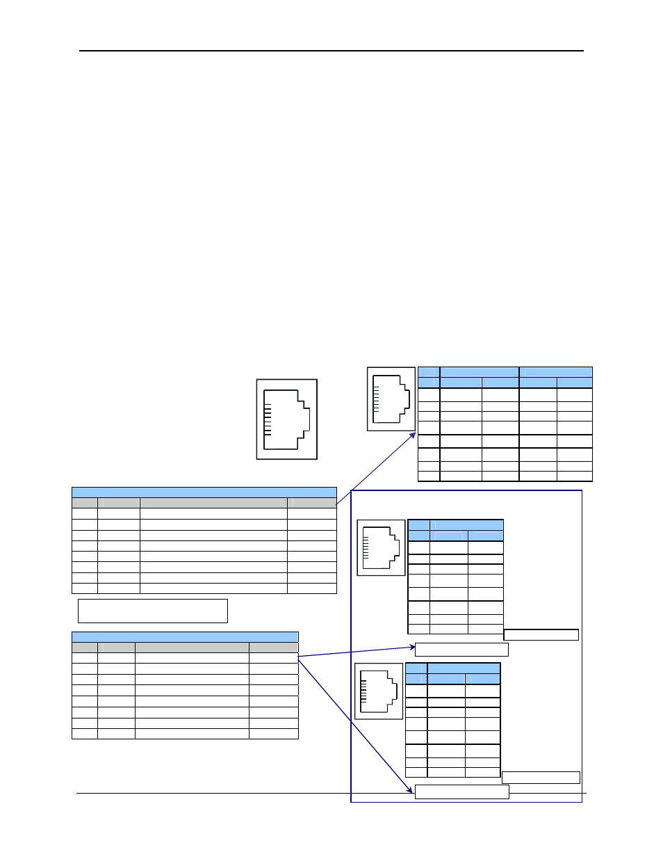
5.3 Wiring
Figure 5-1 along with Table 5.1 and Table 5.2 show how the MJ1 and MJ2 serial
port pins are assigned.
Figure 5-1 – MJ Serial Port Connector
Table 5.1 – MJ1 Serial Port Pin Assignments
Pin
Signal
Signal Description
Direction
1
RX/TX+
RS-485 Receive/Transmit Positive
In/Out
2
RX/TX
− RS-485 Receive/Transmit Negative
In/Out
3 CTS
1
RS-232 Clear to Send
Out
4 RTS
1
RS-232 Request to Send
In
5
+5*
+5 Vdc 60mA max
Out
6 0V
Ground
−
7 TD
1
RS-232
Transmit
Data In
8 RD
1
RS-232 Receive Data
Out
Table 5.2 – – MJ2 Serial Port Pin Assignments
Pin
Signal
Signal Description
Direction
1
RX+
RS-485 Receive Positive
In
2
RX
−
RS-485 Receive Negative
In
3 TX+ RS-485
Transmit
Positive Out
4
TX
−
RS-485 Transmit Negative
Out
5
+5*
+5 Vdc 60mA max
Out
6 0V
Ground
−
7 TD
1
RS-232
Transmit
Data
In
8 RD
1
RS-232 Receive Data
Out
1
Signals are labeled for connection to a DTE device
8
1
Note: MJ1 and MJ2 look the
same but have different pin
assignments and functions.
•
* +5 on XLe Rev E and later
•
* +5 on all revisions XLt
MJ2 Pinouts in Full and Half Duplex Modes
Pin
MJ1 Pins
MJ2 Pins
Signal
Direction
Signal
Direction
8
TXD OUT TXD OUT
7
RXD IN RXD IN
6
0 V
Ground
0 V
Ground
5*
+5 60mA
OUT
+5 60mA
OUT
4
RTS OUT TX- OUT
3
CTS IN TX+
OUT
2
RX- / TX-
IN / OUT
RX-
IN
1
RX+ / TX+
IN / OUT
RX+
IN
1
8
* +5Vdc 60mA Max
Pin
MJ2 Pins
Signal
Direction
8
TXD OUT
7
RXD IN
6
0 V
Ground
5*
+5 60mA
OUT
4
TX- OUT
3
TX+ OUT
2
RX- IN
1
RX+ IN
1
8
MJ2 Full Duplex Mode
MJ2 Half Duplex Mode
Pin
MJ2 Pins
Signal
Direction
8
TXD OUT
7
RXD IN
6
0 V
Ground
5*
+5 60mA
OUT
4
TX- OUT
3
TX+ OUT
2
TX-/RX- IN/OUT
1
TX+/RX+ IN/OUT
1
8
* +5Vdc 60mA Max