Horner APG XLt OCS User Manual
Page 69
MAN0878-04-EN CH. 13
August 12, 2009
Page 69 of 100
ECN # 979
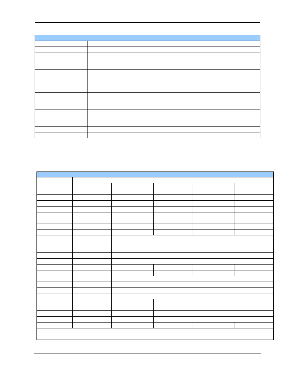
Table 13.2 – Common %SR Register Definitions
%SR164.9
MAKE_CLONE trigger bit
%SR164.10
LOAD_CLONE trigger bit
%SR164.11
Make Clone Fail (This bit goes high when Make / Create Clone fails)
%SR164.12
Load Clone Fail (This bit goes high when Load Clone fails)
%SR175
Status of the removable media
%SR176 to %SR177
This register shows the amount of free space on the inserted removable media
in bytes. This is a 32-bit value.
%SR178 to %SR179
This register shows the total size of the inserted removable media in bytes.
This is a 32-bit value.
%SR181
This register is a bit-mapped indicator of the advanced alarm manager. Each
bit shows if a group has an unacknowledged alarm. For example, if bit one is
ON there is an unacknowledged alarm in group one.
%SR182
This register is a bit-mapped indicator of the advanced alarm manager. Each
bit shows if a group has an active alarm. For example, if bit one is ON there is
an active alarm in group one.
%SR183 (only for XLt)
SYS_BEEP System Beep Enable (0=disabled; 1=enabled)
%SR184 (only for XLt)
USER_BEEP Software configurable (0=OFF; 1=ON)
For additional information on system bits and registers, refer to the on-line help found in Cscape.
13.3
Register Map for XLe/XLt I/O
Table 13.3 – I/O Register Map
Description
Registers
XLx with no I/O XLx with 102 I/O XLx with 103 I/O XLx with 104 I/O XLx with 105 I/O
%I1-%I12
Unused
Digital Inputs
Digital Inputs
Digital Inputs
Digital Inputs
%I13-%I16 Unused
Reserved Reserved Digital
Inputs Reserved
%I17-%I24 Unused
Unused
Reserved Digital
Inputs Reserved
%I25-%I31 Unused
Unused Reserved Reserved Reserved
%I32
Unused
Unused
Output Fault
Output Fault
Output Fault
%Q1-%Q6
Unused
Digital Outputs
Digital Outputs
Digital Outputs
Digital Outputs
%Q7-%Q12
Unused
Reserved
Digital Outputs
Digital Outputs
Digital Outputs
%Q13-%Q16 Unused
Reserved
Reserved Digital
Outputs Reserved
%Q17
Unused
Totalizer: Clear HSC1, Quadrature: Clear Quad1
%Q18
Unused
Totalizer: Clear HSC2, Quadrature: Set Quad1
%Q19
Unused
Totalizer: Clear HSC3, Quadrature: Clear Quad2
%Q20
Unused
Totalizer: Clear HSC4, Quadrature: Set Quad2
%Q21-%Q24 Unused
Reserved
%AI1-%AI2 Unused Analog
Inputs
Analog Inputs
Analog Inputs
Analog Inputs
%AI3-%AI4 Unused Analog
Inputs Reserved Reserved Reserved
%AI5-%AI6 Unused
HSC1
Accumulator
%AI7-%AI8 Unused
HSC2
Accumulator
%AI9-%AI10 Unused
HSC3
Accumulator
%AI11-%AI12 Unused
HSC4
Accumulator
%AQ1-%AQ2
Unused
PWM1 Duty Cycle
%AQ3-%AQ4
Unused
PWM2 Duty Cycle
%AQ5-%AQ6 Unused
PWM
Prescale
%AQ7-%AQ8 Unused
PWM
Period
%AQ9-%AQ10 Unused
Unused
Unused
Unused Analog
Outputs
Unused = These registers can be used as general purpose registers