Horner APG XLt OCS User Manual
Page 43
MAN0878-04-EN CH. 10
August 12, 2009
Page 43 of 100
ECN # 979
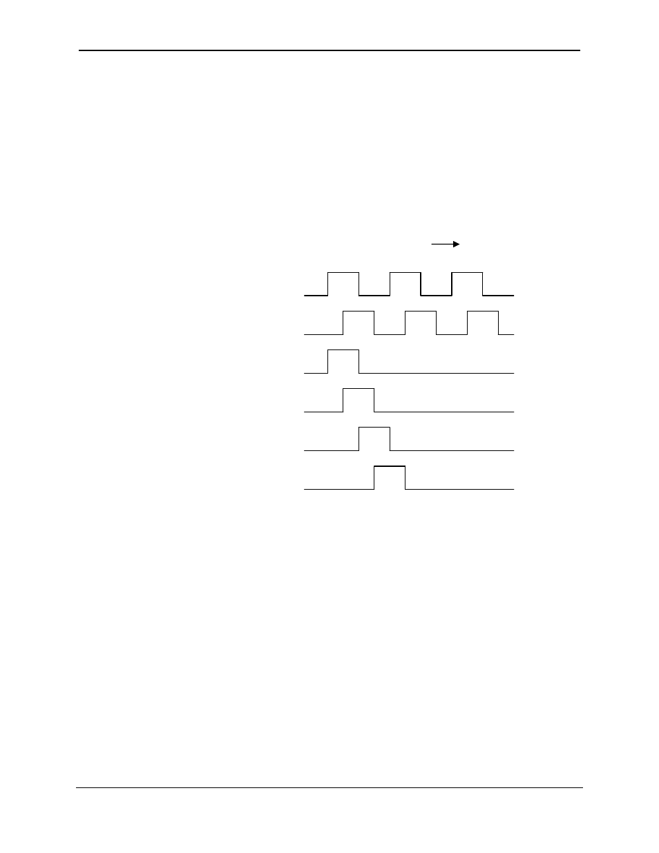
Synchronous modes synchronize the reset (or set) to the selected quadrature input and the
selected marker polarity. Figure 10.1 below indicates which mode to select based on the markers
timing diagram. Consult the documentation provided with your encoder to determine the marker
pulse timing.
Note that the Marker input is sampled within 50 micro seconds of the associated
quadrature edge. It is left to the user to determine if this meets the time
constraints of the measured drive.
Note that if the Marker input pulse consecutively spans more than one of the
specified edges, quadrature-decoding operation is unpredictable.
Sync mode selection
Waveforms (Clockwise Rotation )
__________________________________________________________________
[1]
[2]
High, Reset on 2 rising [SYNC]
High, Reset on 1 falling [SYNC]
High, Reset on 2 falling [SYNC]
High, Reset on 1 rising [SYNC]
*While not displayed in this figure, modes for low level (inverse logic) are also supported
for each state.
Figure 10.1 – Sync pulse mode illustration