Horner APG XLt OCS User Manual
Page 34
CH. 9 MAN0878-04-EN
August 12, 2009
Page 34 of 100
ECN # 979
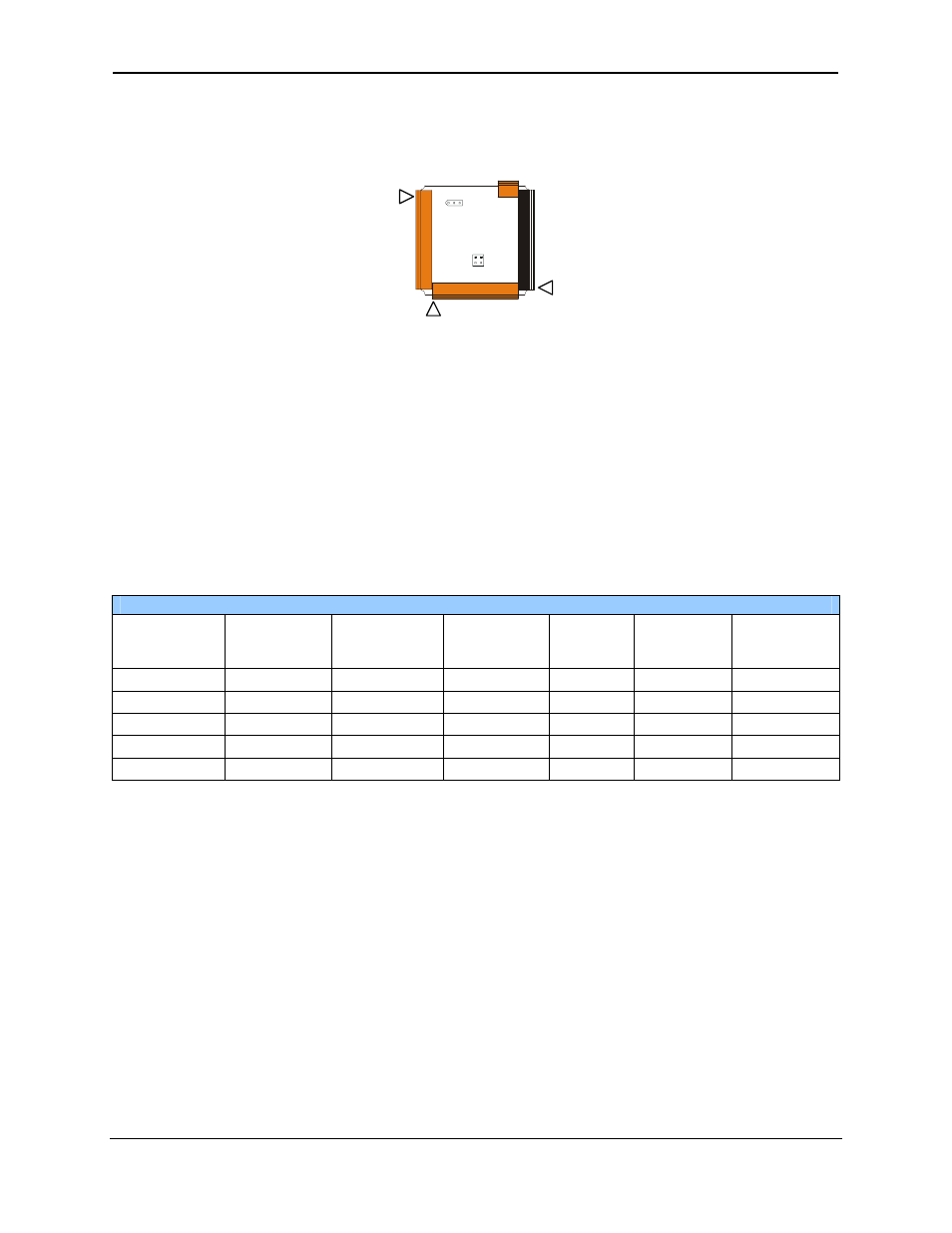
Once the back is removed the jumper selection can be changed. The jumper settings are documented on
each data sheet using a diagram such as Figure 9.2 below and a description of the jumper settings.
Figure 9-2 – Example Jumper Diagram
To re-install the back cover, place the cover back on the unit. The DIN clip should be on the same side
as the power connector.
Place the screw back into the hole and turn the screw slowly counter clockwise until it clicks into the
threads. This prevents the screw from being cross-threaded. Now turn the screw clock-wise until the
cover is firmly secured. Repeat this process for all four (4) screws.
9.3
Model and I/O Overview
Table 9.1 – I/O and Model Overview
Model
(XLe or XLt)
Solid State
Digital
Outputs
Relay
Outputs
Digital
Inputs
Analog
Inputs
Universal
Analog
Inputs
Analog
Outputs
HEXxxx0
HEXxxx2
9
9
9
HEXxxx3
9
9
9
HEXxxx4
9
9
9
HEXxxx5
9
9
9
9
Table 9.1 shows the different types of I/O included with the various XLe/XLt models. Specific
specifications, jumper settings and wiring diagrams can be found on the data sheets attached at
the end of the manual. Descriptions and applications of the different type of I/O can be found
below.
J1
J2
J3
JP3
JP1
001XLE005-R1
J4