Horner APG XLt OCS User Manual
Page 36
CH. 9 MAN0878-04-EN
August 12, 2009
Page 36 of 100
ECN # 979
Relay Life – Relays are mechanical devices that have a long but limited life. Typically switching more
current limits the life of relays. Please check the data sheets at the end of this manual for expected relay
life.
Current / Temperature De-Rating – Products containing relays often have total current limits based on
the ambient temperature of the application. Please see the product data sheet for current / temperature
de-rating information for relays.
Fusing – External fusing is generally required to protect the relays, devices and wiring from shorts or
overloads.
Protection for Inductive Loads – Inductive loads can cause reverse currents when they shut off that can
shorten the life of relay contacts. Some protective measures need to be determined by an engineer.
Below you will find recommendations that will work for many applications. If you have additional
questions on protection from inductive load, consult an application engineer or HEAPG Technical
Support.
DC Loads – General purpose diode (IN4004) in reverse bias across the load.
AC Load – MOV (Harris V140xxx for 120V, V275xx for 220V)
Output State on Controller Stop
When the controller is stopped the operation of each output is configurable. The outputs can hold the
state they were in before the controller stopped or they can go to a predetermined state. By default relay
outputs turn off. For more information on stop state see configuration (Chapter 14) for Cscape settings.
001XLE015
0V ON J1
12-24VDC
R2
C2
R3
C3
R6
C6
R4
C4
R5
C5
R1
C1
H4
H2
H3
LOAD
230VAC
OR
25VDC
N
L
LOAD
230VAC
OR
25VDC
N
L
LOAD
230VAC
OR
25VDC
N
L
LOAD
230VAC
OR
25VDC
N
L
LOAD
230VAC
OR
25VDC
N
L
LOAD
230VAC
OR
25VDC
N
L
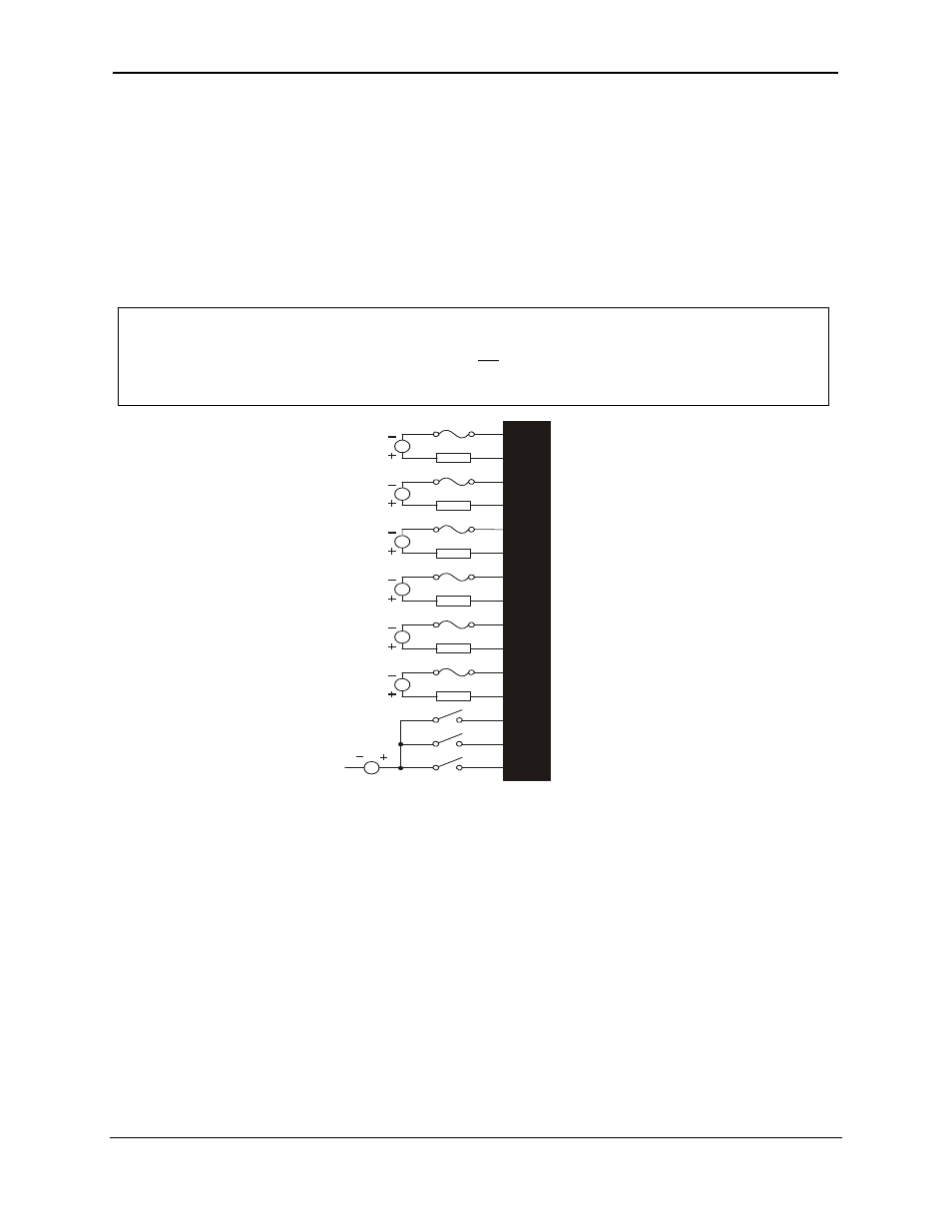
Warning: To protect the module and associated wiring from load faults, use external (5
A)
fuse(s) as
shown. Fuses of lower current or fusing for the entire system need to be in place to assure
the maximum current rating of the unit is not exceeded.
Warning: Connecting high voltage to any I/O pin can cause high voltage to appear at other I/O pins.
Figure 9.4 - Relay Fusing