Horner APG XLt OCS User Manual
Page 48
CH. 10 MAN0878-04-EN
August 12, 2009
Page 48 of 100
ECN # 979
The stepper provides two Boolean registers to provide stepper status
Ready/Done
A high indication on this register (%I30) indicates the stepper sequence can be started (i.e. not
currently busy).
Error
A high indication on this register (%I31) indicates that one of the analog parameters specified
above is invalid or the stepper action was aborted before the operation was complete. This
register is cleared on the next start command if the error was corrected.
The stepper requires one discrete register (%Q1) to control the stepper action. Setting this register starts
the stepper cycle. This register must remain set to complete the entire cycle. Clearing this register
before the cycle is complete aborts the step sequence and sets the error bit.
Note that setting the PLC mode to Stop while the stepper is in operation causes the
stepper output to immediately drop to zero and the current stepper count to be lost.
Note that stepper output level may cause damage or be incompatible with some motor
driver inputs. Consult drive documentation to determine if output level and type is
compatible.
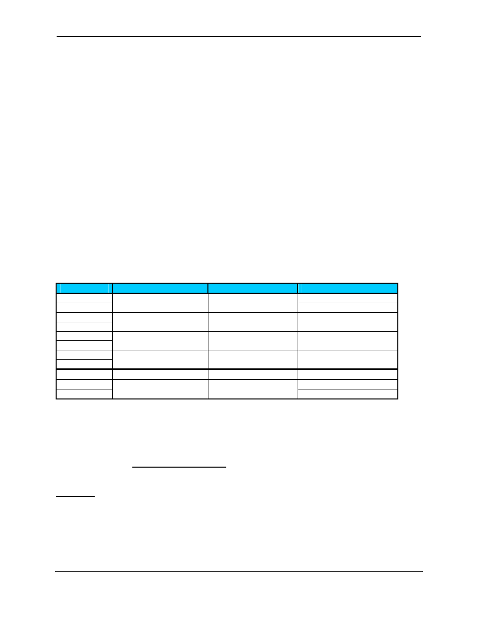
10.5
PWM functions register map
Register
PWM
HSC
Stepper
%AQ1 Start
Frequency
%AQ2
PWM1 Duty Cycle (32-
bit)
HSC1
Preset Value
Run Frequency
%AQ3
%AQ4
PWM2 Duty Cycle (32-
bit)
HSC2
Preset Value
Accel Count
(32-bit)
%AQ5
%AQ6
PWM Prescale
(32-bit)
Run Count
(32-bit)
%AQ7
%AQ8
PWM Period
(32-bit)
Decel Count
(32-bit)
%Q1
Run
%I30 Ready/Done
%I31
Error
10.6
PWM Examples
All of the PWM examples use the following formula.
Frequency =
(
)
t
PeriodCoun
escale
×
+1
Pr
000
,
000
,
16
Example 1
To get a 50% Duty Cycle @ 10 kHz waveform on PWM1:
Set %AQ1-2 = 50 (duty cycle count)
Set %AQ5-6 = 15 (prescale count)
Set %AQ7-8 = 100 (period count)