Horner APG XLt OCS User Manual
Page 68
CH.13 MAN0878-04-EN
August 12, 2009
Page 68 of 100
ECN # 979
%S System Bit
Single-bit bit coils predefined for system use.
%SR System Register
16-bit registers predefined for system use.
%T Temporary Bit
Non-retentive single-bit registers.
13.2
Useful %S and %SR registers
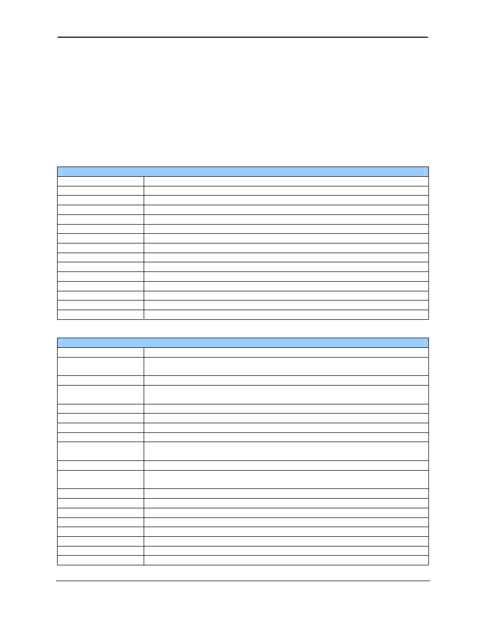
Table 13.1 – Common %S Register Definitions
Register Description
%S1 Indicate
First
Scan
%S2
Network is OK
%S3 10mS
timebase
%S4 100mS
timebase
%S5
1 second timebase
%S6
I/O is OK
%S7 Always
ON
%S8 Always
OFF
%S9
Pause 'n Load soon
%S10
Pause 'n load done
%S11
I/O being forced
%S12
Forcing is enabled
%S13
Network I/O is OK
%S16
Ethernet COM module is OK
Table 13.2 – Common %SR Register Definitions
Register Description
%SR1
This register displays/controls the current user scrollable screen. Setting this
register to 0 displays no user screens
%SR2 This
register
displays/controls the current alarm screen.
%SR6
This register displays the average scan rate of the controller in tenths of
milliseconds. (123 = 12.3 mSec)
%SR44
This register displays the seconds from the real time clock
%SR45
This register displays the minutes from the real time clock.
%SR46
This register displays the hours from the real time clock.
%SR47
This register displays the day of the month from the real time clock.
%SR48
This register displays the month from the real time clock. 1 = January ... 12 =
December.
%SR49
This register displays the four digit year from the real time clock.
%SR50
This register displays the day of the week from the real time clock. 1 =
Sunday, 2 = Monday ... 7 = Saturday
%SR56
This register displays the current key being pressed on the controller keypad.
%SR57
This register displays/controls the LCD backlight. 0 = OFF, non-zero = ON
%SR164.3
Enable Automatic Restore Operation (Fail Safe)
%SR164.4
Enable Backup (Fail Safe System)
%SR164.5
Enable AUTORUN (Fail Safe)
%SR164.6
Enable AUTOLOAD (Fail Safe)
%SR164.7
Clear Backup trigger bit
%SR164.8
Create Backup trigger bit