Horner APG XLt OCS User Manual
Page 45
MAN0878-04-EN CH. 10
August 12, 2009
Page 45 of 100
ECN # 979
10.3
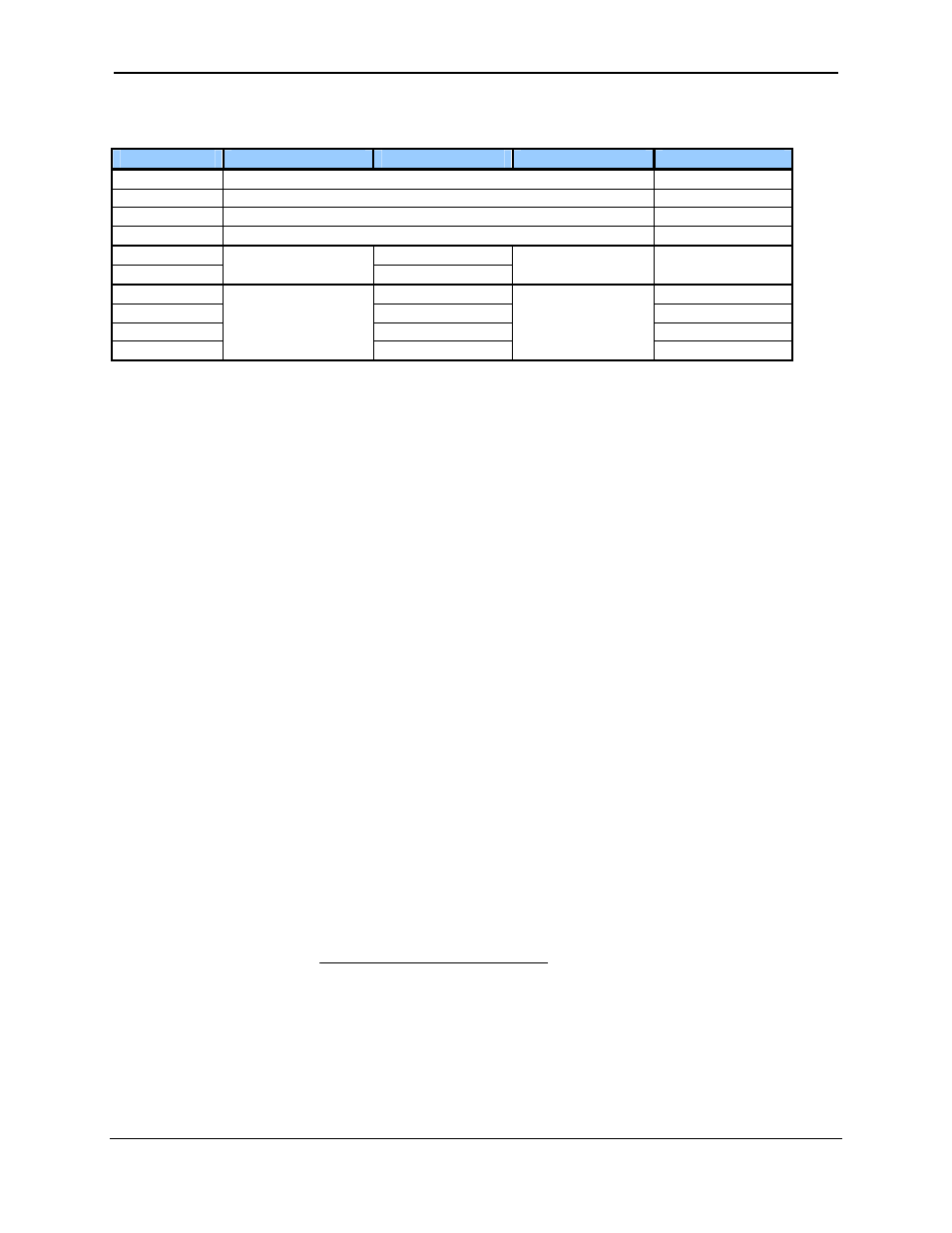
HSC Functions Register Map
Register
Frequency
Totalize
Pulse
Quad
%AI5-6
HSC1 (function) Accumulator
Quad 1 Acc
%AI7-8 HSC2
(function)
Accumulator
%AI9-10
HSC3 (function) Accumulator
Quad 2 Acc
%AI11-12 HSC4
(function)
Accumulator
%AQ1-2 HSC1
Preset
%AQ3-4
HSC2 Preset
%Q17
Clear HSC1
Clear Quad 1
%Q18
Clear HSC2
Set Quad 1
%Q19
Clear HSC3
Clear Quad 2
%Q20
Clear HSC4
Set Quad 2
10.4
Pulse Width Modulation (PWM) Functions
On units that support the PWM, two dedicated outputs are available that can be configured for one of four
modes of operation. Those modes are Normal, PWM, HSC (count = PV) and Stepper.
10.4.1 Normal
When either Q1 or Q2 is configured for Normal operation, the digital output registers %Q1 and
%Q2 drives that respective output.
10.4.2 PWM
When either Q1 or Q2 is configured for PWM, the PWM function drives that respective output.
Both PWM channels may be individually enabled; however, when both PWM outputs are
enabled, both share the same output frequency (with the low going pulses synchronized).
Otherwise, each PWM’s pulse width can be independently adjusted.
The PWMs require three parameters (%AQs) to be set for operation. These parameters may be set at
run-time.
• Prescale
Count
The prescale (%AQ5-6) count sets the resolution of the internal counter used for generating the
PWM output. The (prescale count + 1) is a divisor applied to a 16MHz clock that drives the
internal PWM counter. For the highest resolution PWM output, this value should be set as low as
possible (0 provides a 1/16 micro second resolution). Both the Period and Duty cycle (pulse
width) are based on counts of the internal PWM counter.
The frequency of the PWM output is calculated using the following formula:
Frequency =
(
)
t
PeriodCoun
t
escaleCoun
×
+1
Pr
000
,
000
,
16