Chapter 3 : mechanical installation, Chapter 3: mechanical installation – Horner APG XLt OCS User Manual
Page 15
MAN0878-04-EN CH.3
August 12, 2009
Page 15 of 100
ECN # 979
CHAPTER 3: MECHANICAL INSTALLATION
Note: Each XLe/XLt unit is sent with a datasheet in the box. The datasheet is the first document you
need to refer to for model-specific information related to XLe/XLt models such as pin-outs, jumper
settings, and other key installation information. The web version of this manual has all of the XLe/XLt
datasheets attached to it. Visit our website (see page 96) to obtain datasheets, user documentation, and
updates.
3.1 Overview
The mechanical installation greatly affects the operation, safety and appearance of the system.
Information is provided to mechanically install the unit such as cut-out sizes, mounting procedures and
other recommendations for the proper mechanical installation of the unit.
3.2 Mounting
Requirements
XLe/XLt products can be mounted through a panel or on DIN rail.
3.2.1
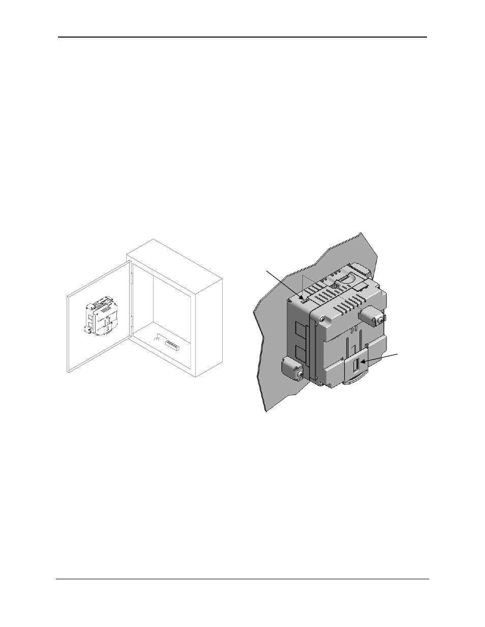
Mounting Procedures (Installed in a Panel Door)
Figure 3-1 – Panel Mounting of the XLe/XLt and Close-up View of Back
Once the panel design has been completed using the criteria and suggestions in the following sections,
use the following steps to panel mount the XLe/XLt.
1. Remove all connectors from the XLe/XLt unit.
2. Press the DIN rail clip up to make passing the unit through the cutout easier.
3. Make sure the gasket is installed on the XLe/XLt and is free from dust and debris. Check that the
corners of the gasket are secure.
4. Pass the unit through the panel.
5. Insert the each of the four (4) mounting clips into the slots in the XLe/XLt case. One clip should be
installed on each corner. Lightly tignten each screw so the clip is held in place.
6. Tighten the screws on the clips such that the gasket is compressed against the panel.
Slot
for Clip
DIN
Rail
001XLE055