GW Instek PSW-Series User Manual User Manual
Page 130
PSW Series User Manual
130
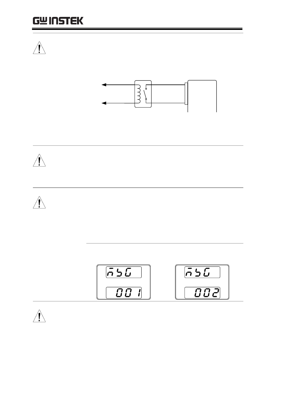
Note
When using a switch over long distances, please
use a switch relay to extend the line from the coil
side of the relay.
Switch
Relay
Line
extention
Analog
connector
Output
Terminal
24
2
If a single switch control is to be used for multiple
units, please isolate each instrument. This can be
achieved by using a relay.
Warning
Ensure the cables used and the switch exceed the
isolation voltage of the power supply. For example:
insulation tubes with a withstand voltage higher
than the power supply can be used.
Note
Messages: If F-94 = 0 (High = on) and the pin 24 is
low (0) “MSG 001” will be displayed on the display.
If F-94 = 1 (Low = on) and the pin 24 is high (1)
“MSG 002” will be displayed on the display.
Output off (High=on)
Output off (Low=on)
Note
Output ON/OFF Delay Time (F-01, F-02) are
disabled when the output is set to external control.
See the normal function settings on 102 for details.
- GDB-03 (99 pages)
- GLA-1000 Series User Manual (111 pages)
- GLA-1000 Series Quick start guide (20 pages)
- GOS-630FC (20 pages)
- GOS-635G (36 pages)
- GOS-6000 Series (27 pages)
- GOS-6103C (30 pages)
- GOS-6100 Series (30 pages)
- GRS-6000A Series (51 pages)
- GDS-122 Installation Guide (4 pages)
- GDS-122 User Manual (52 pages)
- GDS-2000A series CAN/LIN bus User Manual (18 pages)
- GDS-2000A series Quick start guide for DS2-FGN (6 pages)
- GDS-2000A series Freewave User Manual (26 pages)
- GDS-2000A series Quick start guide for Logic analyzer option (18 pages)
- GDS-2000A series Quick start quide for DS2-LAN (2 pages)
- GDS-2000A series Option User Manual (80 pages)
- GDS-2000A series User Manual (261 pages)
- GDS-2000A series Programming Manual (272 pages)
- GDS-2000A series Single sheet for LA Quick start guide (2 pages)
- GBS-1000 Series Programming Manual (88 pages)
- GBS-1000 Series User Manual (187 pages)
- GDS-1000-U Series firmware upgrade (1 page)
- GDS-1000-U Series Programming Manual (70 pages)
- GDS-1000-U Series Quick start guide (2 pages)
- GDS-1000-U Series User Manual (133 pages)
- GDS-1000A-U Series Programming Manual (88 pages)
- GDS-1000A-U Series Quick start guide (2 pages)
- GDS-1000A-U Series User Manual (148 pages)
- GDS-3000 Series GCP-530/1030 current probe User Manual (40 pages)
- GDS-3000 Series GDP-025/050/100 differential probe User Manual (21 pages)
- GDS-3000 Series DS3-PWR Power analysis manual (37 pages)
- GDS-3000 Series User Manual (209 pages)
- GDS-3000 Series Programming Manual (103 pages)
- GDS-3000 Series DS3-SBD Serial Bus decode (29 pages)
- GDS-3000 Series GKT-100 deskew fixture User Manual (1 page)
- GDS-3000 Series GUG-001, GPIB to USB adapter User Manual (15 pages)
- GDS-300 Series User Manual (188 pages)
- GDS-300 Series Programming Manual (139 pages)
- GDS-300 Series Quick start guide (21 pages)
- GRF-3300 Series Student Manual (26 pages)
- GRF-3300 Series Teacher Manual (26 pages)
- GRF-1300A (124 pages)
- GSP-810 User Manual (40 pages)
- GSP-810 Software Manual (3 pages)