Filter time constant, Sensor selection, Set point low limit and high limit – Watlow EZ-ZONE PM User Manual
Page 78
Watlow EZ-ZONE
®
PM Limit Controller
•
75
•
Chapter 8 Features
10. Read Electrical Measurement value [`Mu] of controller via EZ-Configurator or RUI. This will be re-
ferred to as Electrical Measured High. Record high value ______________
11. Calculated Electrical Input Slope = (Precision High – Precision Low) / (Electrical Measured High - Elec-
trical Measured Low). Calculated Slope value ___________
12. Calculated Electrical Input Offset = Precision Low – (Electrical Input Slope * Measured Low). Calculated
Offset value ___________
13. Enter the calculated Electrical Input Slope [ELi;S] and Electrical Input Offset [ELi;o] into the control-
ler.
14. Exit calibration menu.
15. Validate calibration process by utilizing a calibrator to the analog input.
16. Enter calibration offset as recorded in step 2 if required to compensate for sensor error.
Setting Electrical Input Slope [ELi;S] to 1.000 and Electrical Input Offset [ELi;o] to 0.000, restores factory
calibration as shipped from factory.
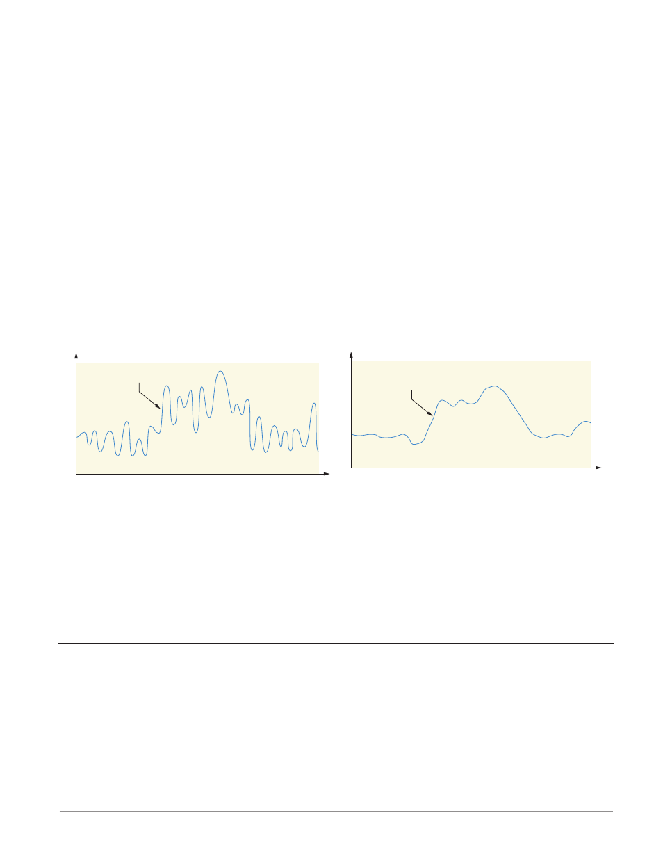
Filter Time Constant
Filtering smoothes an input signal by applying a first-order filter time constant to the signal. Filtering the
displayed value makes it easier to monitor. Filtering the signal may improve the performance of PID control
in a noisy or very dynamic system.
Adjust the filter time interval with Filter Time [`FiL] (Setup Page, Analog Input Menu).
Example: With a filter value of 0.5 seconds, if the process input value instantly changes from 0 to 100 and re-
mained at 100, the display will indicate 100 after five time constants of the filter value or 2.5 seconds.
Sensor Selection
You need to configure the controller to match the input device, which is normally a thermocouple, RTD or
process transmitter. When you select an input device, the controller automatically sets the input linearization
to match the sensor. It also sets high and low limits, which in turn limit the set point range-high and range-
low values.
Select the sensor type with Sensor Type [`Sen] (Setup Page, Analog Input Menu).
Note:
The EZ-ZONE PM does not have an open-sensor detection feature for process inputs.
Set Point Low Limit and High Limit
The controller constrains the Limit set point to a value between the Set Point Low Limit and the Set Point
High Limit.
Set the set point range with Set Point Low Limit [sp;ll] and Set Point HighLimit [sp;lh] (Setup Page,
Loop Menu).
Unfiltered Input Signal
Time
Temperature
Filter Time Constant
Filtered Input Signal
Time
Temperature