Output 4 mechanical relay, form a, Output 4 solid-state relay, form a, Quencharc wiring example – Watlow EZ-ZONE PM User Manual
Page 28: L_ k
Watlow EZ-ZONE
®
PM Limit Controller
•
25
•
Chapter 2 Install and Wire
Warning:
Óç
Use National Electric (NEC) or other
country-specific standard wiring and
safety practices when wiring and
connecting this controller to a power
source and to electrical sensors or
peripheral devices. Failure to do so
may result in damage to equipment
and property, and/or injury or loss
of life.
Note:
Maximum wire size termination and
torque rating:
• 0.0507 to 3.30 mm
2
(30 to 12
AWG) single-wire termination or
two 1.31 mm
2
(16 AWG)
• 0.8 Nm (7.0 lb.-in.) torque
Note:
Adjacent terminals may be labeled
differently, depending on the model
number.
Note:
To prevent damage to the control-
ler, do not connect wires to unused
terminals.
Note:
Maintain electrical isolation be-
tween Analog Input 1, Digital I/O,
Switched dc/open collector outputs
and Process outputs to prevent
ground loops.
Note:
The control output common
terminal and the digital common
terminal are referenced to different
voltages and must remain isolated.
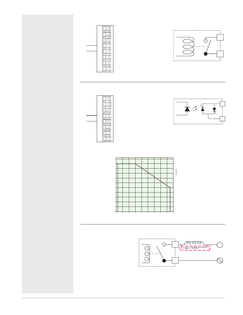
Output 4 Mechanical Relay, Form A
Solid-state Relay
(Ouput 4)
common
normally open
L3
K3
J3
L4
K4
T2
S2
R2
Slot B
• 5 A at 240VÅ (ac) or 30VÎ (dc)
maximum resistive load
• 20 mA at 24V minimum load
• 125 VA pilot duty @ 120/240VÅ
(ac), 25 VA at 24VÅ (ac)
• 100,000 cycles at rated load
• Output does not supply power.
• for use with ac or dc
See Quencharc note.
PM _ _ _ _ _-_ _ _ [J] AAA
L_
K_
Output 4 Solid-State Relay, Form A
Solid-state Relay
(Ouput 4)
common
normally open
L3
K3
J3
L4
K4
T2
S2
R2
Slot B
• 0.5 A at 20 to 264VÅ (ac) maxi-
mum resistive load
• 20 VA 120/240VÅ (ac) pilot duty
• opto-isolated, without contact
suppression
• maximum off state leakage of
105 microamperes
• Output does not supply power.
• Do not use on dc loads.
See Quencharc note.
PM _ _ _ _ _-_ _ _ [K] AAA
K_
L_
1.1
0
-20
50
40
30
20
10
0
-10
60
70
Amps RMS
Ambient Temperature (
o
C)
0.1
1
0.2
0.9
0.3
0.4
0.5
0.6
0.7
0.8
1 Amp SSR Derating Curve
Sa
fe
Operating Area
Quencharc Wiring Example
In this example the Quencharc
circuit (Watlow part# 0804-0147-
0000) is used to protect PM internal
circuitry from the counter electro-
magnetic force from the inductive
user load when de-engergized. It
is recommended that this or an
equivalent Quencharc be used when
connecting inductive loads to PM
outputs.
Quencharc
User Load
N
L_
K_
Quencharc Note:
Switching pilot duty inductive loads
(relay coils, solenoids, etc.) with the
mechanical relay, solid state relay
or open collector output options
requires use of an R.C. suppressor.