Devicenet™ communications, Activity status, Devicenet led indicators – Watlow EZ-ZONE PM User Manual
Page 32: Network status, Module status
Watlow EZ-ZONE
®
PM Limit Controller
•
29
•
Chapter 2 Install and Wire
Warning:
Óç
Use National Electric (NEC) or other
country-specific standard wiring and
safety practices when wiring and
connecting this controller to a power
source and to electrical sensors or
peripheral devices. Failure to do so
may result in damage to equipment
and property, and/or injury or loss
of life.
Note:
Maximum wire size termination and
torque rating:
• 0.0507 to 3.30 mm
2
(30 to 12
AWG) single-wire termination or
two 1.31 mm
2
(16 AWG)
• 0.8 Nm (7.0 lb.-in.) torque
Note:
Adjacent terminals may be labeled
differently, depending on the model
number.
Note:
To prevent damage to the control-
ler, do not connect wires to unused
terminals.
Note:
Maintain electrical isolation be-
tween Analog Input 1, Digital I/O,
Switched dc/open collector outputs
and Process outputs to prevent
ground loops.
Note:
The control output common
terminal and the digital common
terminal are referenced to different
voltages and must remain isolated.
Activity Status
Indicator State
Summary
Requirement
Flashing Green
Detects activity
If the MAC detects activity, the LED will be
flashing green.
Red
- - - -
If the MAC detects a collision, the LED will be
red.
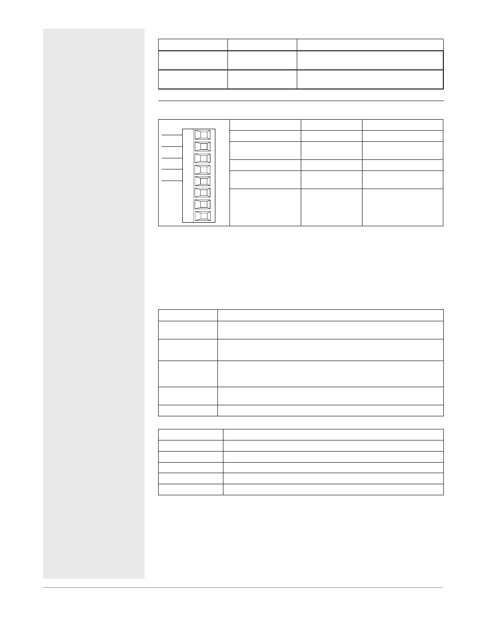
DeviceNet™ Communications
CAN_L
V-
V+
CH
SH
CL
V-
T2
S2
R2
Slot B or E
V+
CAN_H
shield
Terminal
Signal
Function
V+
V+
DeviceNet™ power
CH
CAN_H
positive side of Devi-
ceNet™ bus
SH
shield
shield interconnect
CL
CAN_L
negative side of Devi-
ceNet™ bus
V-
V-
DeviceNet™ power re-
turn
PM [4, 6, 8, 9] _ _ _ _ - [5] _ _ _ _ _ _
DeviceNet LED Indicators
Viewing the control from the front and then looking on top two LEDs can be
seen aligned vertically front to back. The LED closest to the front is identified
as the network (Net) LED where the one next to it would be identified as the
module (Mod) LED.
Network Status
Indicator LED
Description
Off
The device is not online and has not completed the duplicate MAC ID test
yet. The device may not be powered.
Green
The device is online and has connections in the established state (allcated
to a Master).
Red
Failed communication device. The device has detected an error that has
rendered it incapable of communicating on the network (duplicate MAC ID
or Bus-off).
Flashing Green
The device is online, but no connection has been allocated or an explicit
connection has timed out.
Flashing Red
A poll connection has timed out.
Module Status
Indicator LED
Description
Off
No power is applied to the device.
Flashing Green-Red The device is performing a self-test.
Flashing Red
Major Recoverable Fault.
Red
Major Unrecoverable Fault.
Green
The device is operating normally.