Wiring – Watlow EZ-ZONE PM User Manual
Page 19
Watlow EZ-ZONE
®
PM Limit Controller
•
16
•
Chapter 2 Install and Wire
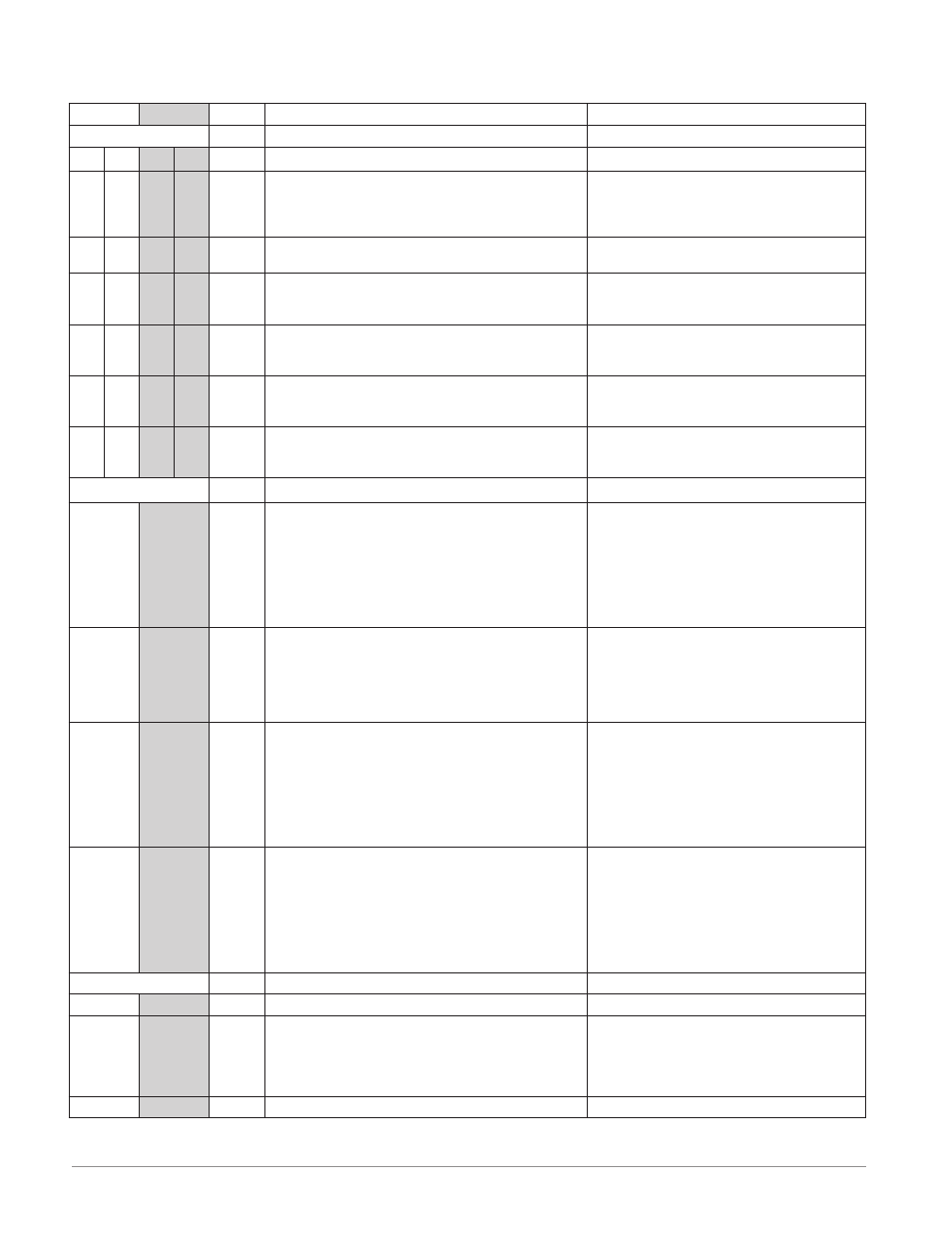
Slot A
Slot B
Slot E
Output
Terminal Function
Configuration
1
2
3
4
X1
W1
Y1
X3
W3
Y3
common (Any switched dc output can use this com-
mon.)
dc- (open collector)
dc+
Switched dc/open collector
output 1: PM [4, 6, 8, 9] _ _ [C] _-_ _ _ _ AAA
output 3: PM [4, 6, 8, 9] _ _ _ _-_ _ [C] _ AAA
W4
Y4
dc-
dc+
Switched dc
output 4: PM [4, 6, 8, 9] _ _ _ _-_ _ _ [C] AAA
F3
G3
H3
voltage or current -
voltage +
current +
Universal Process
output 3: PM [4, 6, 8, 9] _ _ _ _-_ _ [F] _ AAA
L1
K1
J1
L3
K3
J3
normally open
common
normally closed
Mechanical Relay 5 A, Form C
output 1: PM [4, 6, 8, 9] _ _ E _-_ _ _ _ AAA
output 3: PM [4, 6, 8, 9] _ _ _ _-_ _ [E] _ AAA
L2
K2
L4
K4
normally open
common
Mechanical Relay 5 A, Form A
output 2: PM [4, 6, 8, 9] _ _ _ J-_ _ _ _ AAA
output 4: PM [4, 6, 8, 9] _ _ _ _-_ _ _ [J] AAA
L3
K3
L4
K4
normally open
common
Solid-state Relay 0.5 A, Form A
output 3: PM [4, 6, 8, 9] _ _ _ _-_ _ [K] _ AAA
output 4: PM [4, 6, 8, 9] _ _ _ _-_ _ _ [K] AAA
Communications
CB
CA
CC
CB
CA
C5
C3
C2
CB
CA
CC
CB
CA
C5
C3
C2
Modbus RTU EIA-485 T+/R+
Modbus RTU EIA-485 T-/R-
Modbus RTU EIA-485 common
Modbus RTU EIA-485 T+/R+
Modbus RTU EIA-485 T-/R-
Modbus RTU EIA-232 common
Modbus RTU EIA-232 to DB9 pin 2
Modbus RTU EIA-232 to DB9 pin 3
Modbus RTU 232/485 Communications
Slot B:
PM6 _ _ _ _-[2] A A A AAA
Slot E:
PM [4, 8, 9] _ _ _ _-[2] A A A AAA
V+
CH
SH
CL
V-
V+
CH
SH
CL
V-
DeviceNet™ power
Positive side of DeviceNet™ bus
Shield interconnect
Negative side of DeviceNet™ bus
DeviceNet™ power return
DeviceNet™ Communications
Slot B:
PM6 _ _ _ _-[5] A A A AAA
Slot E:
PM [4, 8, 9] _ _ _ _-[5] A A A AAA
E8
E7
E6
E5
E4
E3
E2
E1
E8
E7
E6
E5
E4
E3
E2
E1
EtherNet/IP™ and Modbus TCP unused
EtherNet/IP™ and Modbus TCP unused
EtherNet/IP™ and Modbus TCP receive -
EtherNet/IP™ and Modbus TCP unused
EtherNet/IP™ and Modbus TCP unused
EtherNet/IP™ and Modbus TCP receive +
EtherNet/IP™ and Modbus TCP transmit -
EtherNet/IP™ and Modbus TCP transmit +
Ethernet 10/100 supporting EtherNet/IP™
and Modbus TCP
Slot B:
PM6 _ _ _ _-[3] A A A AAA
Slot E:
PM [4, 8, 9] _ _ _ _-[3] A A A AAA
VP
B
A
DG
trB
B
A
trA
VP
B
A
DG
trB
B
A
trA
Voltage Potential
EIA-485 T+/R+
EIA-485 T-/R-
Digital ground (common)
Termination resistor B
EIA-485 T+/R+
EIA-485 T-/R-
Termination resistor A
Profibus Communications
Slot B:
PM6 _ _ _ _-[6] A A A AAA
Slot E:
PM [4, 8, 9] _ _ _ _-[6] A A A AAA
Inputs
1
T1
S1
R1
S2 (RTD) or current +
S3 (RTD), thermocouple -, current -, volts - or poten-
tiometer wiper, thermistor
S1 (RTD), thermocouple + or volts +, thermistor, po-
tentiometer
Universal Sensor
input 1: all configurations
Slot A
Slot B
Slot E
Wiring