Conventions used in the menu pages – Watlow EZ-ZONE PM User Manual
Page 41
Watlow EZ-ZONE
®
PM Limit Controller
•
38
•
Chapter 4 Home Page
Conventions Used in the Menu Pages
To better understand the menu pages that follow review the naming conventions used. When encountered
throughout this document, the word "default" implies as shipped from the factory. Each page (Operations,
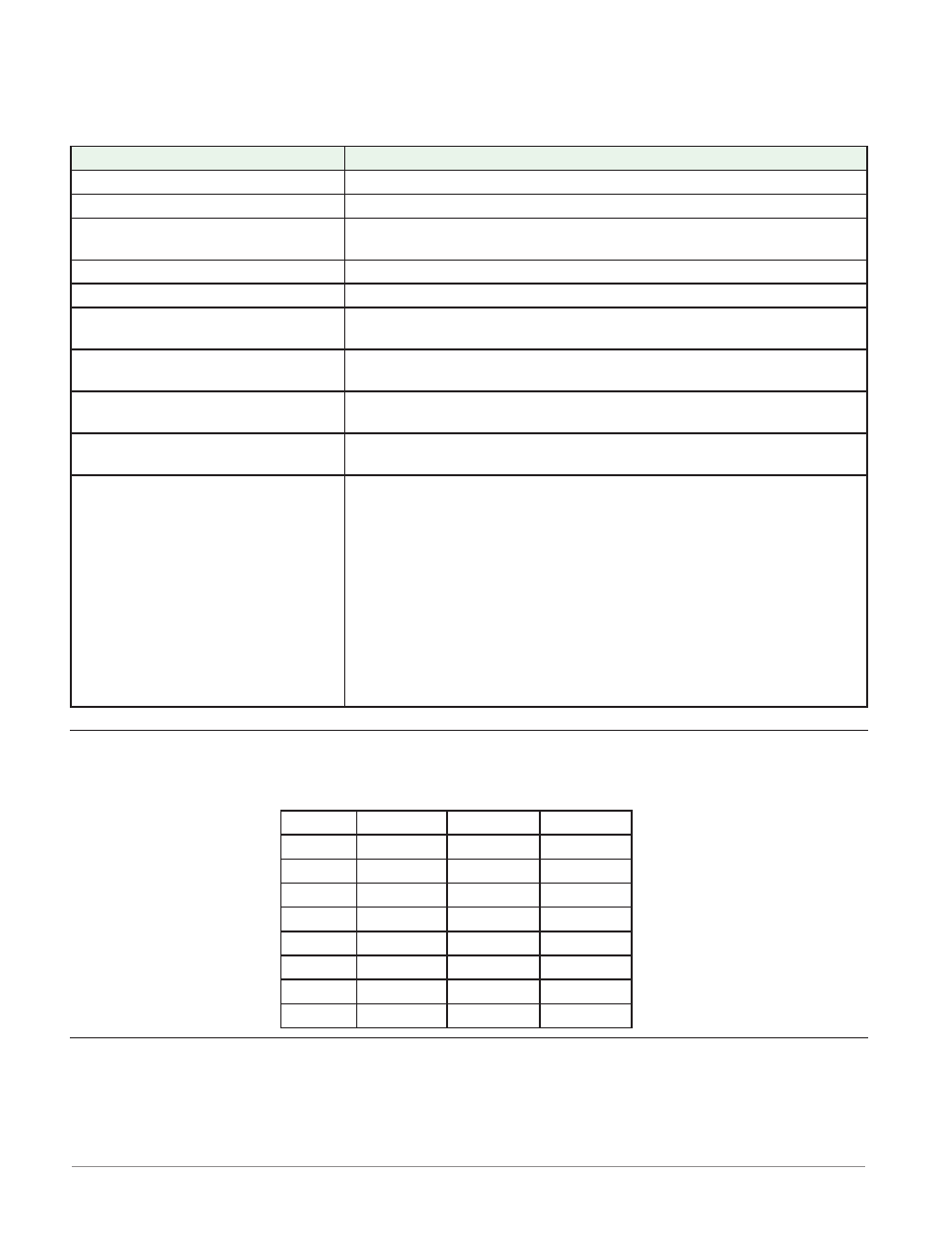
Setup, Profile and Factory) and their associated menus have identical headers defined below:
Header Name
Definition
Display
Visually displayed information from the control.
Parameter Name
Describes the function of the given parameter.
Range
Defines options available for this prompt, i.e., min/max values (nu-
merical), yes/no, etc... (further explanation below).
Default
Values as delivered from the factory.
Parameter Appears in Menu When
Conditions required for parameter to appear in menu.
Modbus Relative Address
Identifies unique parameters using either the Modbus RTU or Mod-
bus TCP protocols (further explanation below).
CIP (Common Industrial Protocol)
Identifies unique parameters using either the DeviceNet or Ether-
Net/IP protocol (further explanation below).
Profibus Index
Identifies unique parameters using Profibus DP protocol (further ex-
planation below).
Parameter ID
Identifies unique parameters used with other software such as, Lab-
VIEW.
Data Type R/W
uint = Unsigned 16 bit
integer
dint = long, 32-bit
string = ASCII (8 bits
per character)
float = IEEE 754 32-bit
RWES = Readable
Writable
EEPROM (saved)
User Set (saved)
Display
Visual information from the control is displayed to the observer using a fairly standard 7 segment display.
Due to the use of this technology, several characters displayed need some interpretation, see the list below:
[1]
= 1
[0]
= 0
[i]
= i
[r]
= r
[2]
= 2
[a ]
= A
[j ]
= J
[s]
= S
[3]
= 3
[ b]
= b
[H]
= K
[ t]
= t
[4]
= 4
[c]
, [C] = c
[ l]
= L
[U]
= u
[5]
= 5
[d ]
= d
[ m ]
= M
[u]
= v
[6]
= 6
[ e]
= E
[n]
= n
[ w ]
= W
[7]
= 7
[ f]
= F
[o]
= o
[y ]
= y
[8]
= 8
[g ]
= g
[ p]
= P
[2]
= Z
[9]
= 9
[ h]
= h
[q ]
= q
Range
Within this column notice that on occasion there will be numbers found within parenthesis. This number rep-
resents the enumerated value for that particular selection. Range selections can be made simply by writing
the enumerated value of choice using any of the available communications protocols. As an example, turn to
the Setup Page and look at the Analog Input [`Ai] menu and then the Sensor Type [Sen] prompt. To turn
the sensor off simply write the value of 62 (off) to Modbus register 400369 and send that value to the control.