Installation – Watlow EZ-ZONE PM User Manual
Page 17
Watlow EZ-ZONE
®
PM Limit Controller
•
14
•
Chapter 2 Install and Wire
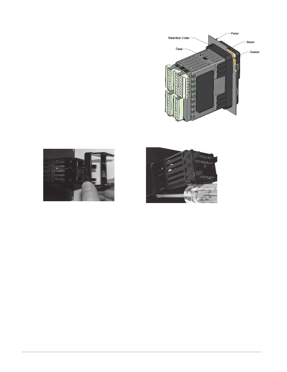
Installation
1. Make the panel cutout using the mounting template dimen-
sions in this chapter.
Insert the case assembly into the panel cutout.
2. While pressing the case assembly firmly against the panel,
slide the mounting collar over the back of the controller.
If the installation does not require a NEMA 4X seal, simply
slide together until the gasket is compressed.
3. For a NEMA 4X (UL50, IP66) seal, alternately place and
push the blade of a screwdriver against each of the the four
corners of the mounting collar assembly. Apply pressure to
the face of the controller while pushing with the screwdriver.
Don't be afraid to apply enough pressure to properly install
the controller. The seal system is compressed more by mat-
ing the mounting collar tighter to the front panel (see pic-
tures above). If you can move the case assembly back and
forth in the cutout, you do not have a proper seal. The tabs
on each side of the mounting collar have teeth that latch into the ridges on the sides of the controller.
Each tooth is staggered at a different depth from the front so that only one of the tabs, on each side, is
locked onto the ridges at a time.
Slide the mounting collar over the back of the
controller .
Place the blade of a screwdriver in any
of the corner of the mounting collar as-
sembly .
Note:
There is a graduated measurement difference between the upper and lower half of the display to the panel.
In order to meet the seal requirements mentioned above, ensure that the distance from the front of the top
half of the display to the panel is 16 mm (0.630 in.) or less, and the distance from the front of the bottom
half and the panel is 13.3 mm (0.525 in.) or less.