Low power, High power, Digital input 5, 6 – Watlow EZ-ZONE PM User Manual
Page 22
Watlow EZ-ZONE
®
PM Limit Controller
•
19
•
Chapter 2 Install and Wire
Warning:
Óç
Use National Electric (NEC) or other
country-specific standard wiring and
safety practices when wiring and
connecting this controller to a power
source and to electrical sensors or
peripheral devices. Failure to do so
may result in damage to equipment
and property, and/or injury or loss
of life.
Note:
Maximum wire size termination and
torque rating:
• 0.0507 to 3.30 mm
2
(30 to 12
AWG) single-wire termination or
two 1.31 mm
2
(16 AWG)
• 0.8 Nm (7.0 lb.-in.) torque
Note:
Adjacent terminals may be labeled
differently, depending on the model
number.
Note:
To prevent damage to the control-
ler, do not connect wires to unused
terminals.
Note:
Maintain electrical isolation be-
tween Analog Input 1, Digital I/O,
Switched dc/open collector outputs
and Process outputs to prevent
ground loops.
Note:
The control output common
terminal and the digital common
terminal are referenced to different
voltages and must remain isolated.
Low Power
Power
power
power
98
99
CF
CD
CE
B5
D6
D5
Slot C
fuse
• Minimum/Maximum Ratings
• 12 to 40VÎ (dc)
• 20 to 28VÅ (ac) Semi Sig F47
• 47 to 63 Hz
• 14VA maximum power consumption (PM4, 8 & 9)
• 10VA maximum power consumption (PM3 & 6)
PM_ _ [3, 4] _ _ - _ _ _ _ _ _ _
High Power
Power
power
power
98
99
CF
CD
CE
B5
D6
D5
Slot C
fuse
• Minimum/Maximum Ratings
• 85 to 264VÅ (ac)
• 100 to 240VÅ (ac) Semi Sig F47
• 47 to 63 Hz
• 14VA maximum power consumption (PM4, 8 & 9)
• 10VA maximum power consumption (PM3 & 6)
PM_ _ [1, 2] _ _ - _ _ _ _ _ _ _
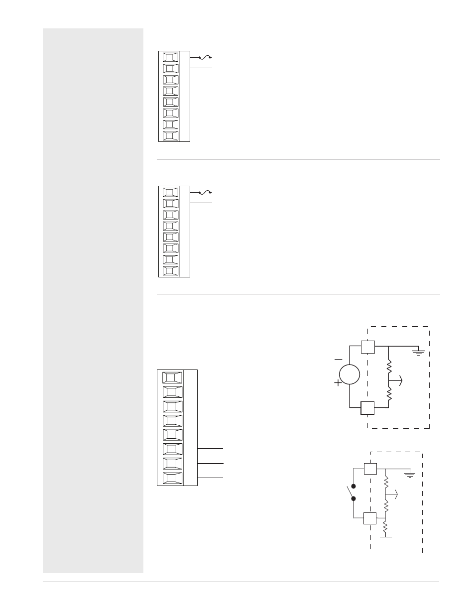
Digital Input 5, 6
input 5
common -
98
99
CF
CD
CE
B5
D6
D5
Slot C
input 6
Digital Input
• Update rate 10 Hz
• Dry contact or dc voltage
DC Voltage
• Input not to exceed 36V at 3
mA
• Input active when > 3V @ 0.25
mA
• Input inactive when < 2V
Dry Contact
• Input inactive when > 500 Ω
• Input active when < 100 Ω
• maximum short circuit 13 mA
PM _ _ [2,4] _ _-_ _ _ _ _ _ _
Voltage Input
Vdc
common
B
_
D
_
Dry Contact
common
24 Vdc
B
_
_
D