Profibus dp communications, Profibus dp led indicators, Closest to the front – Watlow EZ-ZONE PM User Manual
Page 33
Warning:
Óç
Use National Electric (NEC) or other
country-specific standard wiring and
safety practices when wiring and
connecting this controller to a power
source and to electrical sensors or
peripheral devices. Failure to do so
may result in damage to equipment
and property, and/or injury or loss
of life.
Note:
Maximum wire size termination and
torque rating:
• 0.0507 to 3.30 mm
2
(30 to 12
AWG) single-wire termination or
two 1.31 mm
2
(16 AWG)
• 0.8 Nm (7.0 lb.-in.) torque
Note:
Adjacent terminals may be labeled
differently, depending on the model
number.
Note:
To prevent damage to the control-
ler, do not connect wires to unused
terminals.
Note:
Maintain electrical isolation be-
tween Analog Input 1, Digital I/O,
Switched dc/open collector outputs
and Process outputs to prevent
ground loops.
Note:
The control output common
terminal and the digital common
terminal are referenced to different
voltages and must remain isolated.
Watlow EZ-ZONE
®
PM Limit Controller
•
30
•
Chapter 2 Install and Wire
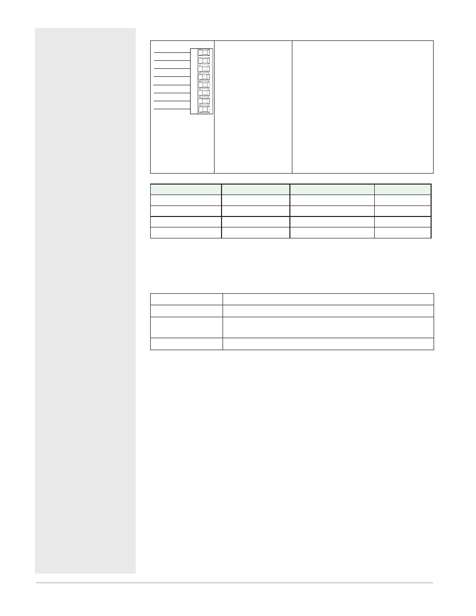
Profibus DP Communications
485 T-/R-
+5Vdc Voltage Potential
VP
B
A
DG
trB
B
A
trA
Slot B & E
485 T+/R+
Digital ground
Termination resistor B
485 T+/R+
485 T-/R-
Termination resistor A
• Wire T-/R- to the A
terminal of the EIA-
485 port.
• Wire T+/R+ to the B
terminal of the EIA-
485 port.
• Wire Digital Ground
to the common ter-
minal of the EIA-485
port.
• Do not route network
wires with power
wires. Connect net-
work wires in daisy-
chain fashion when
connecting multiple
devices in a network.
• A termination resistor should be used if
this control is the last one on the network.
• If using a 150 Ω cable Watlow provides in-
ternal termination. Place a jumper across
pins trB and B and trA and A.
• If external termination is to be used with a
150 Ω cable place a 390 Ω re-sistor across
pins VP and B, a 220 Ω resistor across pins
B and A, and lastly, place a 390 Ω resistor
across pins DG and A.
• Do not connect more than 32 EZ-ZONE
PM
controllers on any given segment.
• Maximum EIA-485 network length: 1,200
meters (4,000 feet)
• 1/8th unit load on EIA-485 bus.
PM
[4, 6, 8, 9] _ _ _ _-[6] AAA AAA
Profibus Terminal
EIA/TIA-485 Name
Watlow Terminal Label
Function
VP (Voltage Potential)
- - - -
VP
+5Vdc
B-Line
B
B
T+/R+
A-Line
A
A
T-/R-
DP-GND
common
DG
common
Profibus DP LED Indicators
Viewing the unit from the front and then looking on top of the RUI/GTW two
bi-color LEDs can be seen where only the front one is used. Definition follows:
Closest to the Front
Indicator LED
Description
Red
Profibus network not detected
Red
Flashing
Indicates that the Profibus card is waiting for data ex-
change.
Green
Data exchange mode