Standard bus eia-485 communications, Modbus rtu or standard bus eia-485 communications – Watlow EZ-ZONE PM User Manual
Page 29
Warning:
Óç
Use National Electric (NEC) or other
country-specific standard wiring and
safety practices when wiring and
connecting this controller to a power
source and to electrical sensors or
peripheral devices. Failure to do so
may result in damage to equipment
and property, and/or injury or loss
of life.
Note:
Maximum wire size termination and
torque rating:
• 0.0507 to 3.30 mm
2
(30 to 12
AWG) single-wire termination or
two 1.31 mm
2
(16 AWG)
• 0.8 Nm (7.0 lb.-in.) torque
Note:
Adjacent terminals may be labeled
differently, depending on the model
number.
Note:
To prevent damage to the control-
ler, do not connect wires to unused
terminals.
Note:
Maintain electrical isolation be-
tween Analog Input 1, Digital I/O,
Switched dc/open collector outputs
and Process outputs to prevent
ground loops.
Note:
The control output common
terminal and the digital common
terminal are referenced to different
voltages and must remain isolated.
Watlow EZ-ZONE
®
PM Limit Controller
•
26
•
Chapter 2 Install and Wire
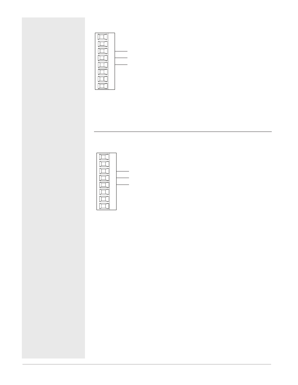
Standard Bus EIA-485 Communications
Standard Bus
EIA-485
T-/R-
common
98
99
CF
CD
CE
B5
D6
D5
Slot C
T+/R+
• Wire T-/R- to the A terminal of
the EIA-485 port.
• Wire T+/R+ to the B terminal of
the EIA-485 port.
• Wire common to the common
terminal of the EIA-485 port.
• Do not route network wires
with power wires. Connect net-
work wires in daisy-chain fash-
ion when connecting multiple
devices in a network.
• Do not connect more than 16
EZ-ZONE PM controllers on a
network.
• Maximum network length:
1,200 meters (4,000 feet)
• 1/8th unit load on EIA-485 bus
PM _ _ _ _ _-[A, 2 or 3] _ _ _ AAA
Note:
Do not leave a USB to EIA-485 converter connected to Standard Bus with-
out power (i.e., disconnecting the USB end from the computer while leaving
the converter connected on Standard Bus). Disturbance on the Standard
Bus may occur.
Modbus RTU or Standard Bus EIA-485 Communications
Modbus RTU or
Standard Bus EIA-485
T-/R-
common
98
99
CC
CA
CB
B5
D6
D5
Slot C
T+/R+
• Wire T-/R- to the A terminal of
the EIA-485 port.
• Wire T+/R+ to the B terminal of
the EIA-485 port.
• Wire common to the common
terminal of the EIA-485 port.
• Do not route network wires
with power wires. Connect net-
work wires in daisy-chain fash-
ion when connecting multiple
devices in a network.
• A termination resistor may be
required. Place a 120 Ω resistor
across T+/R+ and T-/R- of last
controller on network.
• Only one protocol per port is
available at a time: either Mod-
bus RTU or Standard Bus.
• Do not connect more than 16
EZ-ZONE PM controllers on a
Standard Bus network.
• Maximum number of EZ-ZONE
controllers on a Modbus RTU
network is 247.
• Maximum network length:
1,200 meters (4,000 feet)
• 1/8th unit load on EIA-485 bus.
PM _ _ _ _ _-[1] _ _ _ AAA
Note:
Do not leave a USB to EIA-485 converter connected to Standard Bus with-
out power (i.e., disconnecting the USB end from the computer while leaving
the converter connected on Standard Bus). Disturbance on the Standard
Bus may occur.