Gilderfluke&Co Mp3-50 Audio & Show Controllers User Manual
Page 38
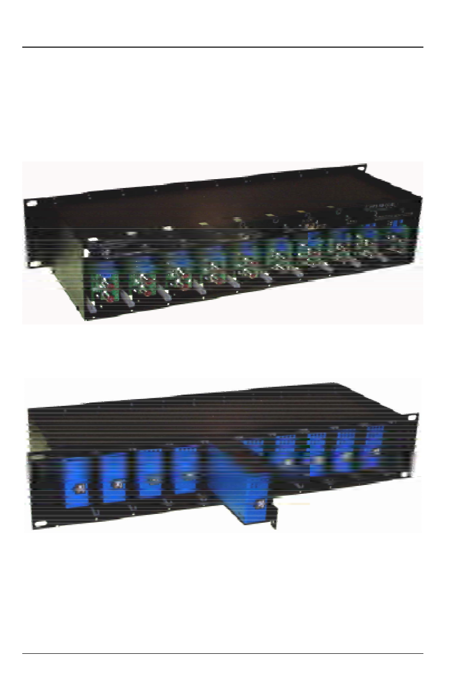
The same two screws which you removed are inserted through the
same holes through the connector card of the Mp3-50, but going the op-
posite direction. These two screws are then used to hold the connector
card into the Mp3-50/CC-10 (the cards and the screws are installed
through the front of the cage). As the connector card is plugged in to the
backplane, make sure that all twelve pins of J2 are inserted correctly into
the mating connector on the backplane of the Mp3-50/CC-10.
Now the Mp3-50, Mp3-50/8 or Mp3-50/40 can be plugged into the
card cage. Nothing else needs to be removed or changed on the Mp3-50,
Mp3-50/8 or Mp3-50/40 before they inserted into the Mp3-50/CC-10.
Power can be wired into any of the card cage positions, or through the
heavy current screw terminals. The latter should be used if you are using
the amplifiers or Show Control outputs on Mp3-50/8 or Mp3-50/40 cards.
This is because the total current draw can exceed the capacity of the 2.1
mm power connector or smaller screw terminals located on the back of
each Mp3-50.
The DMX-512/MIDI serial port is daisy chained from higher numbered
G
ILDERFLUKE
& C
O
.• 205 S
OUTH
F
LOWER
S
TREET
• B
URBANK
, C
ALIFORNIA
91502 • 818/840-9484 • 800/776-5972 •
FAX
818/840-9485
E
AST
C
OAST
/F
LORIDA
O
FFICE
• 7041 G
RAND
N
ATIONAL
D
RIVE
• S
UITE
128d • O
RLANDO
, F
L
. 32819 • 407/354-5954 •
FAX
407/354-5955
30 of 119