Gilderfluke&Co Mp3-50 Audio & Show Controllers User Manual
Page 33
If attaching discrete wires from the J6 ribbon cable connector
presents a problem, we have forty and ten position transition con-
nectors are available for the Mp3-50/8s or Mp3-50/40s to adapt
the ribbon cables to screw terminals. Ribbon cable to screw termi-
nal adapters are also available from a number of different
sources.
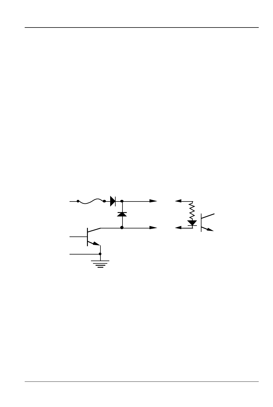
Any eight digital devices or one eight-bit analog device can
be connected to any 1/4 J-6 cable as shown. The LED between
the ground (pin #1 brown) wire and supply (pin #10 black) wire
acts as an indicator that is lit if the fuse for that channel is OK.
All outputs are open collector switches to ground. Small fly-
back diodes are included in the outputs for driving inductive
loads. Larger inductive loads may require flyback diodes be in-
stalled directly across the loads. Power is supplied through a diode
and a solid state circuit breaker to the common pin(s) on the con-
nector. A safe level of current is 150 milliamperes simultaneously
on each output. This is sufficient to drive most small relays, valves
and other similar loads directly. If fewer than eight outputs are on
at one time, then the outputs are rated as follows.
typical output
typical input
fuse
flyback
diode
supply
supply
The supply line for each 1/4 J-6 is PTC fused for 1 amp. You
should treat each 1/4 J-6 as an individual, and not cross the out-
puts or supply lines from one channel to the lines from any other
channel. Doing this won’t cause any damage, but can reduce
the protection for the outputs that the fuses normally provide.
The current Output Capacity of each output is as shown in
the following chart:
G
ILDERFLUKE
& C
O
.• 205 S
OUTH
F
LOWER
S
TREET
• B
URBANK
, C
ALIFORNIA
91502 • 818/840-9484 • 800/776-5972 •
FAX
818/840-9485
E
AST
C
OAST
/F
LORIDA
O
FFICE
• 7041 G
RAND
N
ATIONAL
D
RIVE
• S
UITE
128d • O
RLANDO
, F
L
. 32819 • 407/354-5954 •
FAX
407/354-5955
25 of 119