10 totalizer block (tot) – Micromod MOD: 1800P - MOD 30ML Identity Module (Version 2) Algorithms, Tables and Sequential Logic Functions User Manual
Page 97
Logic Functions - Book 2
Totalizer Block
8-89
8.10
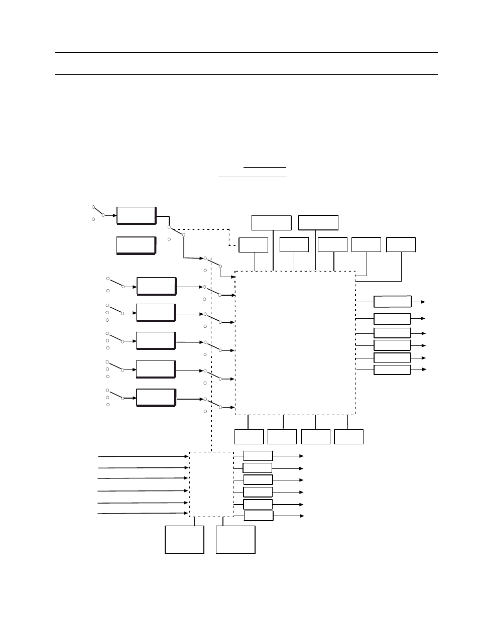
TOTALIZER BLOCK (TOT)
The totalizer block can count an analog input signal by converting the linear analog variable
into a number of discrete pulses that are accumulated as a total count. The totalizer has a
range of 0.0 to 9999999.0. An input threshold value may be configured to avoid the totalization
of extraneous low-level signals. The totalizer function can have an UP or DOWN direction. In
the UP direction, the new count is added to the current total count. In the DOWN direction, the
new count is subtracted from the total count. The calculation is shown below along with a
functional diagram of the block in Figure 8-48. The Totalizer displays used to configure the
block are shown in Figures 8-49 and 8-51.
TotalCount
TotalCount
or
Input
ElapsedTime
Rate
ScaleFactor
=
+ −
×
Input
Type
Auto Wrap
Rate
Command
Threshold
Quality Check
HLSTAT
Total
Count (TC)
Reset Input
Direction Input
Scale
Factor
TCQ
HLSTATQ
LLSTATQ
PC1STATQ
PC2STATQ
MODEQ
Stop Input
Analog
Input
Pulse Input
(future)
Discrete LSP
Discrete Value
None
LLSTAT
PC1STAT
PC2STAT
MODE
Discrete LSP
Discrete Value
None
Run Input
Discrete LSP
Discrete Value
None
Hold Input
Discrete LSP
Discrete Value
None
Restart
Mode
High
Limit
Low
Limit
Predetermined
Count 1
Predetermined
Count 2
Analog Input LSP Quality
Direction Input LSP Quality
Reset Input LSP Quality
Stop Input LSP Quality
Run Input LSP Quality
Hold Input LSP Quality
Bad Inputs
Accepted
(YES, NO)
State
(RUN, HOLD,
OFF, DEBUG)
Totalizer Calculation
(see timing diagrams)
Figure 8-48. Functional Block Diagram, Totalizer