3 input communication block (ic) – Micromod MOD: 1800P - MOD 30ML Identity Module (Version 2) Algorithms, Tables and Sequential Logic Functions User Manual
Page 25
Logic Functions - Book 2
INPUT COMMUNICATION BLOCK
8-17
8.3
INPUT COMMUNICATION BLOCK (IC)
The input communication block is used to receive data from the output communication block,
or output communication block channel for MOD 30 controllers and recorders, or another
instrument on the ICN via communication messages. The block specifies the source, data
type, and whether quality is to be received with the data. It also has the capability of receiving
other MOD 30 data types and storing the data as a MODCELL data type; for example,
continuous may be received and floating point stored. A mode switch is available so that the
data being received can be ignored, and allow an operator to manually change the data.
Finally, two diagnostics are provided. One diagnostic (source diagnostic) is provided to detect
a configuration error within either the block or within an Output Communication block in
another instrument. The other (timeout diagnostic) is provided to detect a break in the
communications that has halted the continual flow of data from the source.
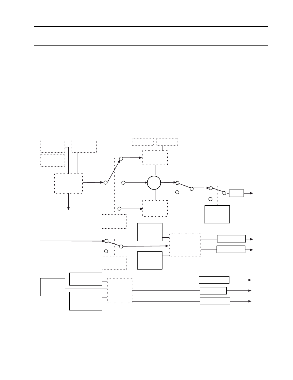
Block outputs are the data and data quality and diagnostic errors and error quality. A
functional block diagram of a input communication block is shown in Figure 8-7. Displays used
to configure the Input Communication block are shown in Figures 8-8 through Figure 8-10.
ASCII or
HEX
Input Data
Quality
MANUAL
AUTO
Data
Source
Bad Inputs
Accepted
(YES)
BAD
GOOD
Quality Check
State (RUN,
HOLD, OFF,
DEBUG)
Continuous
Port
Number
Occurrence
Number
NO
YES
Receive
Quality
Instrument
Number
Top
Bottom
Maximum
Field Size
(1-126)
Range
OR
All others
Diagnostic
Group
(None, 1 - 7)
Not Receiving
Data (Enab/Supp)
Receiving
Unexpected Data
(Enab/Supp)
Diagnostic
Errors
Data
Type
TO:
Diagnostic
Errors
Result
Result Quality
Error Quality
Error Count
Active Errors
Unacked Errors
Mode
Figure 8-7. Functional Block Diagram, Input Communication Block