Output communication block operation, Output communication block parameters – Micromod MOD: 1800P - MOD 30ML Identity Module (Version 2) Algorithms, Tables and Sequential Logic Functions User Manual
Page 35
Logic Functions - Book 2
OUTPUT COMMUNICATION BLOCK
8-27
8.4.1
Output Communication Block Operation
The Output Communication block is a loop function block that writes the ICN send buffer every
time the instrument gains access to transmit (approximately every 250 milliseconds).
When the mode is in auto, the input and its quality are fetched, and placed in the result and
result quality fields respectively. If the data was updated, from either the input source or a
write message (manual only), then the message buffer is updated for the next transmission
cycle. The data will not be updated when the communication lock is true.
On a warm start, a message is formatted with the current data value. On a cold start, data
quality is set to bad, the send buffer is cleared, and nothing is sent until the block executes
and the communication lock is false.
8.4.2
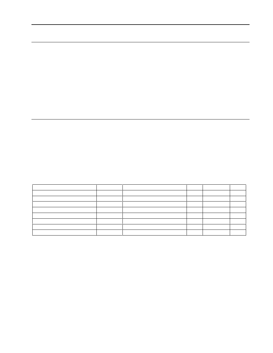
Output Communication Block Parameters
The mnemonics, valid values, and data types for all fields that may be selected for display
and/or be used in making softwiring connections are listed in Table 8-3. The following further
defines the output communication block configuration parameters.
Block Type
OC
This is the output communication block type.
Occurrence
1 to 32 There may be up to 32 ‘instances’ allowed of the OC block type.
Table 8-3. Output Communication Block Attributes, Valid Values, Mnemonics, and Data Types
Field Name /
Attribute
Mnemonic
Valid Values
CWR
Data Type
Attr
Version
VERSION
– – R Long State
00
Block Length
BLKLEN
– – R Count
01
Block State
STATE
RUN, HOLD, OFF, DEBUG
CWR Short State
02
Bad Inputs Accepted
BADINP
YES
– – R Discrete
03
Data Update Mode
MODE
AUTO, MANUAL
CWR Discrete
04
Initial Data (Result)
R
local data
CWR any
05
Result Quality
RQ
GOOD, BAD
– WR Discrete
06
Input
INPUT
LSP, local data
CWR any
07
Data Destination ................................................................................................................C – –
The data source information is configured in this block and is used to define the source of the
incoming data.
Instrument Number
Instrument Numbers are: 0 to 15. This number represents the
ICN address of the instrument receiving the data.
Port Number
Port Numbers are: 1 to 3. This number represents which ICN
block should transmit the data.
Send Quality
NO - Data quality is not sent with the data. Quality data can
not processed by MOD 30 instruments
YES - Data quality is sent with the data (for MODCELL
instruments).