Micromod MOD: 1800P - MOD 30ML Identity Module (Version 2) Algorithms, Tables and Sequential Logic Functions User Manual
Page 63
Logic Functions - Book 2
TIMER BLOCK
8-55
Operator
Reset Command
Time
3
2
1
0
0
30
25
20
15
10
5
35
4
3.5
1.5
True
False
False
True
ON
OFF
Reset Input
Disable
High Limit
Status
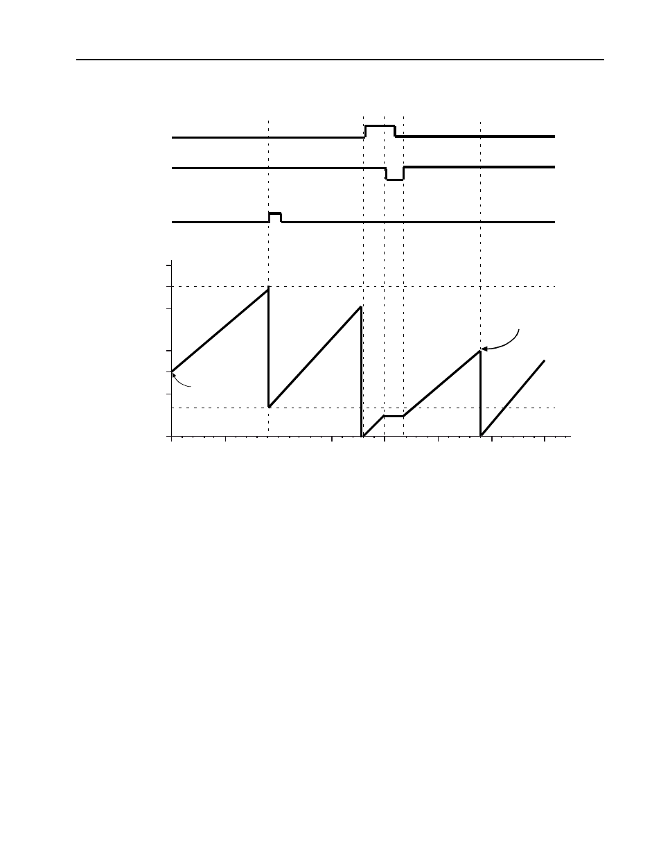
TIMER DIRECTION: UP with WRAP
Timer Value
Timer Initial Value
Timer High Limit
Timer Low Limit
Reset Value
Figure 8-29. Timing Diagram, Up Timer with WRAP = TRUE
The timer can be reset via the reset input or the reset command. The reset input causes the
timer to be reset when a rising edge is detected. The reset command message resets the
timer when the message is received (TRUE value written to the reset command attribute).
When a reset occurs, the time value is set to the value of the reset value input. The timer will
begin timing (if not disabled and not beyond the limit) with the very next execution cycle. If the
reset value is beyond the limit, the limit status will be set when the timer is reset.
Since the timer block is effectively timing the interval between the previous and current
execution cycles, the direction and disable inputs have a delayed effect on the timer function.
That is, both of these inputs will effect the function of the timer on the next execution. The
timer adds or subtracts the time interval to its running time based on the value of the direction
on the previous execution. If the disable input becomes TRUE, the timer adds the most recent
interval to its running time, then discontinues adding in the time intervals until the next scan
cycle after the disable input becomes FALSE.