Ds1874 sfp+ controller with digital ldd interface – Rainbow Electronics DS1874 User Manual
Page 83
DS1874
SFP+ Controller with Digital LDD Interface
______________________________________________________________________________________
83
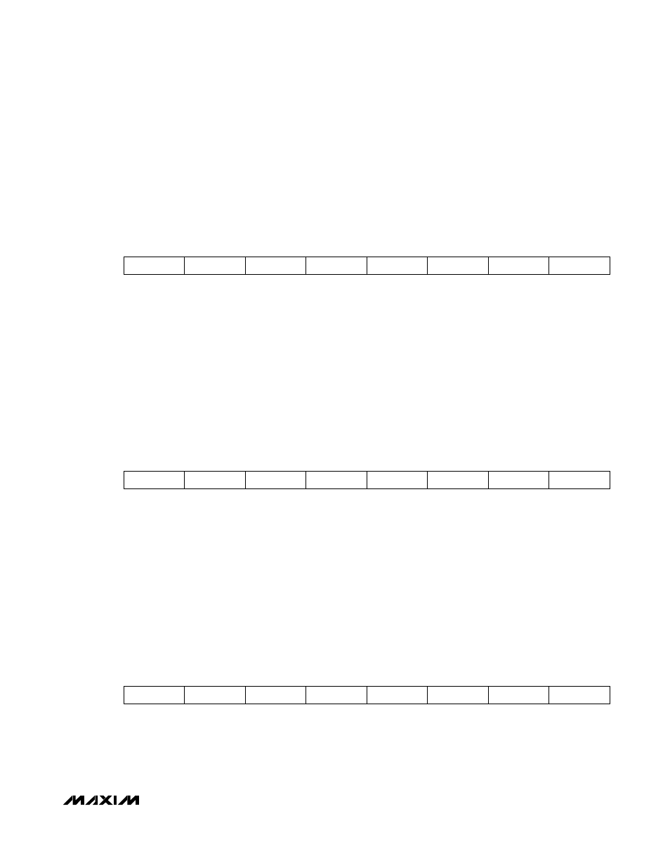
Table 02h, Register FAh: WRITE
FACTORY
DEFAULT
00h
READ ACCESS
PW2 or (PW1 and RWTBL246) or (PW1 and RTBL246)
WRITE ACCESS
PW2 or (PW1 and RWTBL246)
MEMORY
TYPE Volatile
FAh 2
7
2
6
2
5
2
4
2
3
2
2
2
1
2
0
BIT
7
BIT
0
This byte is used during manual 3-wire communication. When a manual write is initiated, this register contain s
the data for the operation.
FACTORY
DEFAULT
00h
READ ACCESS
PW2 or (PW1 and RWTBL246) or (PW1 and RTBL246)
WRITE
ACCESS N/A
MEMORY TYPE
Volatile
FBh 2
7
2
6
2
5
2
4
2
3
2
2
2
1
2
0
BIT
7
BIT
0
This byte is used during maunual 3-wire communication. When a manual read is initiated, the return data is
stored in this register.
FACTORY
DEFAULT
00h
READ ACCESS
PW2 or (PW1 and RWTBL246) or (PW1 and RTBL246)
WRITE
ACCESS N/A
MEMORY
TYPE Volatile
FCh 2
7
2
6
2
5
2
4
2
3
2
2
2
1
2
0
BIT
7
BIT
0
MAX3798/MAX3799 register. This value is read from the MAX3798/MAX3799 with the 3-wire interface every t
RR
(see the MAX3798/MAX3799 electrical characteristics).
Table 02h, Register FBh: READ
Table 02h, Register FCh: TXSTAT1