Figure 7. rssi flowchart, Table 4. mon3 hysteresis threshold values, Table 5. mon3 configuration registers – Rainbow Electronics DS1874 User Manual
Page 18: Ds1874 sfp+ controller with digital ldd interface
DS1874
SFP+ Controller with Digital LDD Interface
18
______________________________________________________________________________________
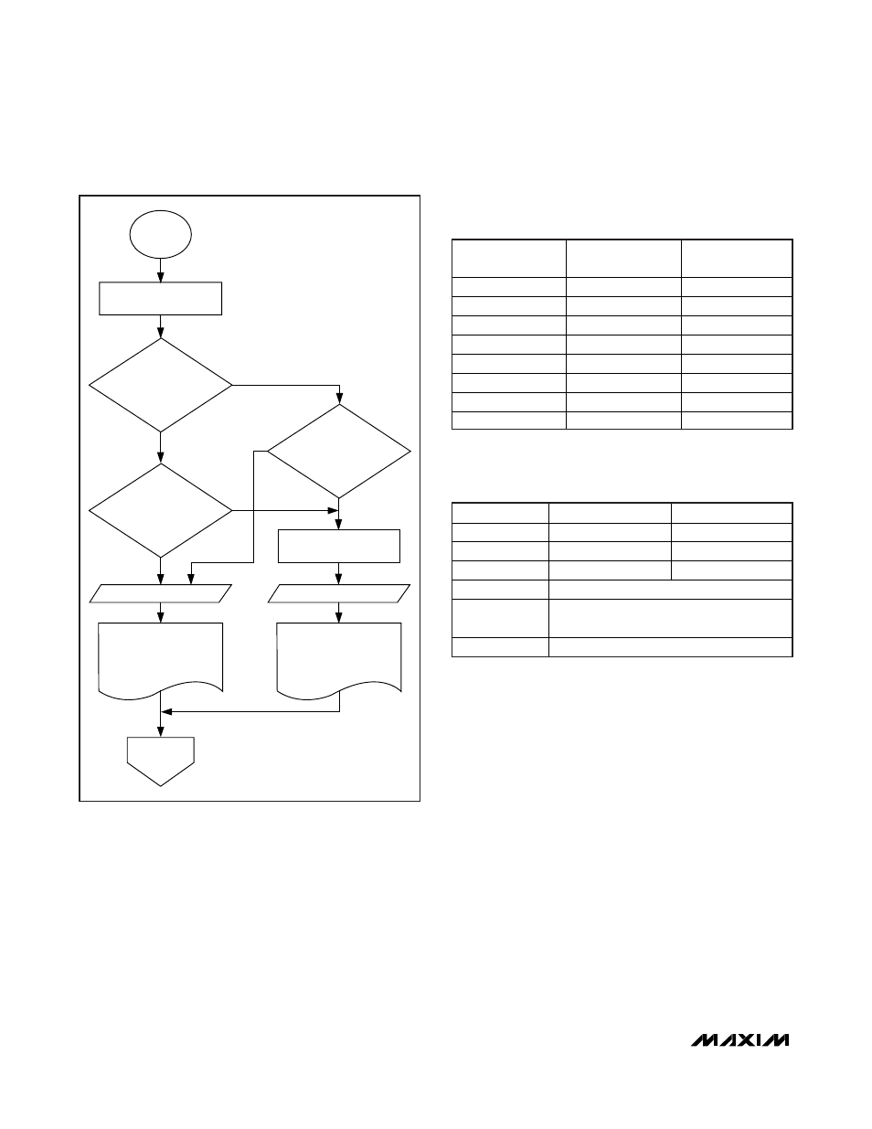
Then, depending on whether the last MON3 timeslice
resulted in a coarse-mode conversion and also depend-
ing on the value of the current fine conversion, decisions
are made whether to use the current fine-mode conver-
sion result or to make an additional conversion (within
the same MON3 timeslice), using coarse mode (using
coarse mode’s gain and offset settings and no right-
shifting) and reporting the coarse-mode result. The flow-
chart in Figure 7 also illustrates how hysteresis is
implemented. The fine-mode conversion is compared to
one of two thresholds. The actual threshold values are a
function of the number of right-shifts being used. With
the use of right-shifting, the fine mode full-scale is pro-
grammed to (1/2
N
th) of the coarse mode full-scale. The
DS1874 now auto ranges to choose the range that gives
the best resolution for the measurement. Hysteresis is
applied to eliminate chatter when the input resides at
the boundary of the two ranges. See Figure 7 for details.
Table 4 shows the threshold values for each possible
number of right-shifts.
The RSSI_FF and RSSI_FC bits are used to force fine-
mode or coarse-mode conversions, or to disable the
dual-range functionality. Dual-range functionality is
enabled by default (both RSSI_FC and RSSI_FF are
factory programmed to 0 in EEPROM). It can be dis-
abled by setting RSSI_FC to 0 and RSSI_FF to 1. These
bits are also useful when calibrating MON3. For addi-
tional information, see Figure 19.
Table 5. MON3 Configuration Registers
REGISTER
FINE MODE
COARSE MODE
GAIN
98h–99h, Table 02h 9Ch–9Dh, Table 04h
OFFSET
A8h–A9h, Table 02h ADh–ACh, Table 04h
RIGHT-SHIFT
0
8Fh, Table 04h
—
CNFGC
8Bh, Table 02h
CONFIG
(RSSIS BIT)
77h, Lower Memory
MON3 VALUE
68h–69h, Lower Memory
NUMBER OF
RIGHT-SHIFTS
FINE MODE
MAX (hex)
COARSE MODE
MIN* (hex)
0 FFF8
F000
1 7FFC
7800
2 3FFE
3C00
3 1FFF
1E00
4 0FFF
0F00
5 07FF
0780
6 03FF
03C0
7 01FF
01E0
MON3
TIMESLICE
END OF MON3
TIMESLICE
PERFORM FINE-
MODE CONVERSION
REPORT FINE
CONVERSION RESULT
REPORT COARSE
CONVERSION RESULT
DID PRIOR MON3
TIMESLICE RESULT IN A
COARSE CONVERSION?
(LAST RSSI = 1?)
LAST RSSI = 0
LAST RSSI = 1
WAS CURRENT FINE-
MODE CONVERSION
≥ 93.75% OF FS?
PERFORM COARSE-
MODE CONVERSION
DID CURRENT FINE-
MODE CONVERSION
REACH MAX?
N
Y
Y
Y
N
N
Figure 7. RSSI Flowchart
Table 4. MON3 Hysteresis Threshold
Values
*
This is the minimum reported coarse-mode conversion.