Transmit fault (txf) output, Die identification, Wire master for controllin – Rainbow Electronics DS1874 User Manual
Page 22: Protocol, Wire master for controlling the max3798/max3799, Figure 13. logic diagram 2, Figure 14a. txf nonlatched operation, Figure 14b. txf latched operation, Ds1874, Sfp+ controller with digital ldd interface
DS1874
same signals and faults can also be used to generate
the internal signal FETG (Table 01h/05h, Registers FAh
and FBh). FETG is used to send a fast “turn-off” com-
mand to the laser driver. The intended use is a direct
connection to the MAX3798/MAX3799’s TXD input if
this is desired. When V
CC
< POA, TXDOUT is high
impedance.
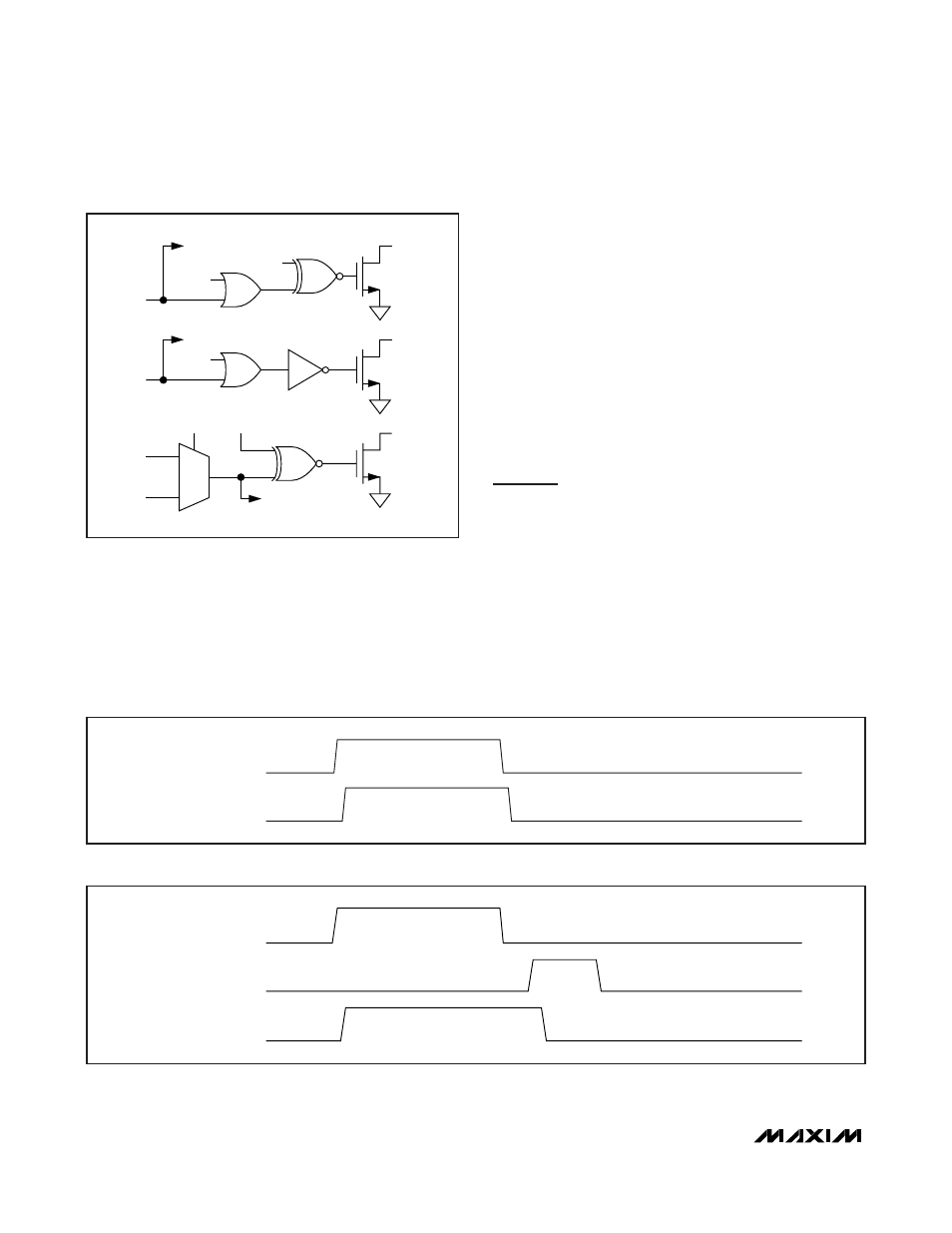
Transmit Fault (TXF) Output
TXF can be triggered by all alarms, warnings, and
quick trips (Figure 12). The six ADC alarms, warnings,
and the LOS quick trips require enabling (Table
01h/05h, Registers F8h and FDh). See Figures 14a and
14b for nonlatched and latched operation. Latching of
the alarms is controlled by the CNFGB and CNFGC
registers (Table 02h, Registers 8Ah–8Bh).
Die Identification
The DS1874 has an ID hardcoded in its die. Two regis-
ters (Table 02h, Registers CEh–CFh) are assigned for
this feature. The CEh register reads 74h to identify the
part as the DS1874, while the CFh register reads the
current device version.
3-Wire Master for Controlling
the MAX3798/MAX3799
The DS1874 controls the MAX3798/MAX3799 over a
proprietary 3-wire interface. The DS1874 acts as the
master, initiating communication with and generating
the clock for the MAX3798/MAX3799. It is a 3-pin inter-
face consisting of SDAOUT (a bidirectional data line),
an SCLOUT clock signal, and a CSELOUT chip-select
output (active high).
Protocol
The DS1874 initiates a data transfer by asserting the
CSELOUT pin. It then starts to generate a clock signal
22
______________________________________________________________________________________
DETECTION OF TXF FAULT
TXD
TXF
Figure 14b. TXF Latched Operation
INVOUT1
IN1C
IN1
IN1S
OUT1
INV LOS
LOSC
MUX
LOSOUT
RSELOUT
RSELC
RSEL
LOS
LOS LO
RSELS
RXL
SFP+ Controller with Digital LDD Interface
DETECTION OF TXF FAULT
TXF
Figure 14a. TXF Nonlatched Operation
Figure 13. Logic Diagram 2