Enhanced rssi monitoring (du, Figure 5. adc round-robin timing, Ds1874 sfp+ controller with digital ldd interface – Rainbow Electronics DS1874 User Manual
Page 17
DS1874
SFP+ Controller with Digital LDD Interface
______________________________________________________________________________________
17
TEMP
V
CC
MON1
MON2
MON3
MON4
TEMP
ONE ROUND-ROBIN ADC CYCLE
t
RR
NOTE: IF THE VCC LO ALARM IS ENABLED AT POWER-UP, THE ADC ROUND-ROBIN TIMING CYCLES BETWEEN TEMPERATURE AND V
CC
ONLY UNTIL V
CC
IS ABOVE THE V
CC
ALARM LOW THRESHOLD.
the measurement is increased by a factor of 8, and
because the result is digitally divided by 8 by right-
shifting, the bit weight of the measurement still meets
the standard’s specification (i.e., SFF-8472).
The right-shift operation on the ADC result is carried out
based on the contents of right-shift control registers (Table
02h, Registers 8Eh–8Fh) in EEPROM. Four analog chan-
nels, MON1–MON4, each have 3 bits allocated to set the
number of right-shifts. Up to seven right-shift operations
are allowed and are executed as a part of every conver-
sion before the results are compared to the high-alarm
and low-alarm levels, or loaded into their corresponding
measurement registers (Lower Memory, Registers
64h–6Bh). This is true during the setup of internal calibra-
tion as well as during subsequent data conversions.
Enhanced RSSI Monitoring (Dual-Range
Functionality)
The DS1874 offers a feature to improve the accuracy
and range of MON3, which is most commonly used for
monitoring RSSI. The accuracy of the RSSI measure-
ments is increased at the small cost of reduced range
(of input signal swing). The DS1874 eliminates this
trade-off by offering “dual range” calibration on the
MON3 channel (see Figure 6). This feature enables
right-shifting (along with its gain and offset settings)
when the input signal is below a set threshold (within the
range that benefits using right-shifting) and then automat-
ically disables right-shifting (recalling different gain and
offset settings) when the input signal exceeds the thresh-
old. Also, to prevent “chattering,” hysteresis prevents
excessive switching between modes in addition to ensur-
ing that continuity is maintained. Dual-range operation is
enabled by default (factory programmed in EEPROM).
However, it can easily be disabled through the RSSI_FC
and RSSI_FF bits, which are described in the
Register
Descriptions
section. When dual-range operation is dis-
abled, MON3 operates identically to the other MON
channels, although featuring a differential input.
Dual-range functionality consists of two modes of opera-
tion: fine mode and coarse mode. Each mode is calibrat-
ed for a unique transfer function, hence the term, dual
range. Table 5 highlights the registers related to MON3.
Fine mode is equivalent to the other MON channels. Fine
mode is calibrated using the gain, offset, and right-shift-
ing registers at locations shown in Table 5 and is ideal
for relatively small analog input voltages. Coarse mode is
automatically switched to when the input exceeds a
threshold (to be discussed in a subsequent paragraph).
Coarse mode is calibrated using different gain and offset
registers, but lacks right-shifting (since coarse mode is
only used on large input signals). The gain and offset
registers for coarse mode are also shown in Table 5.
Additional information for each of the registers can be
found in the
Register Descriptions
section.
Dual-range operation is transparent to the end user.
The results of MON3 analog-to-digital conversions are
still stored/reported in the same memory locations
(68h–69h, Lower Memory) regardless of whether the
conversion was performed in fine mode or coarse
mode. The only way to tell which mode generated the
digital result is by reading the RSSIS bit.
When the DS1874 is powered up, analog-to-digital con-
versions begin in a round-robin fashion. Every MON3
timeslice begins with a fine mode analog-to-digital con-
version (using fine mode’s gain, offset, and right-shifting
settings). See the flowchart in Figure 7 for more details.
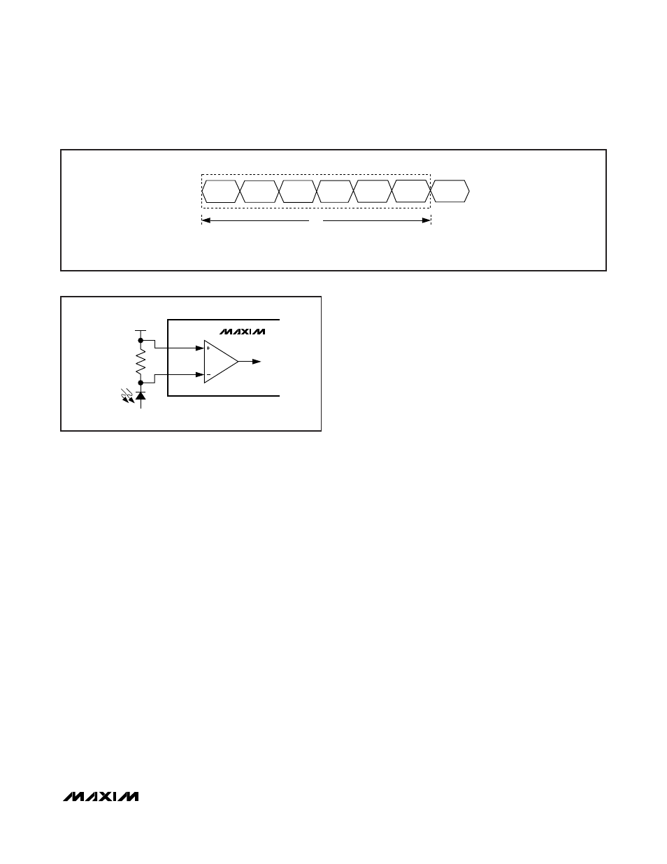
DS1874
MON3P
MON3N
ADC
100
Ω
ROSA
V
CC
Figure 6. MON3 Differential Input for High-Side RSSI
Figure 5. ADC Round-Robin Timing