Figure 9. recommended rc filter for dac1/dac2, Figure 10. delta-sigma outputs, Figure 11. dac1/dac2 lut assignments – Rainbow Electronics DS1874 User Manual
Page 20: Ds1874, Sfp+ controller with digital ldd interface
DS1874
is either manually controlled or controlled using a tem-
perature-indexed LUT. A delta-sigma is a digital output
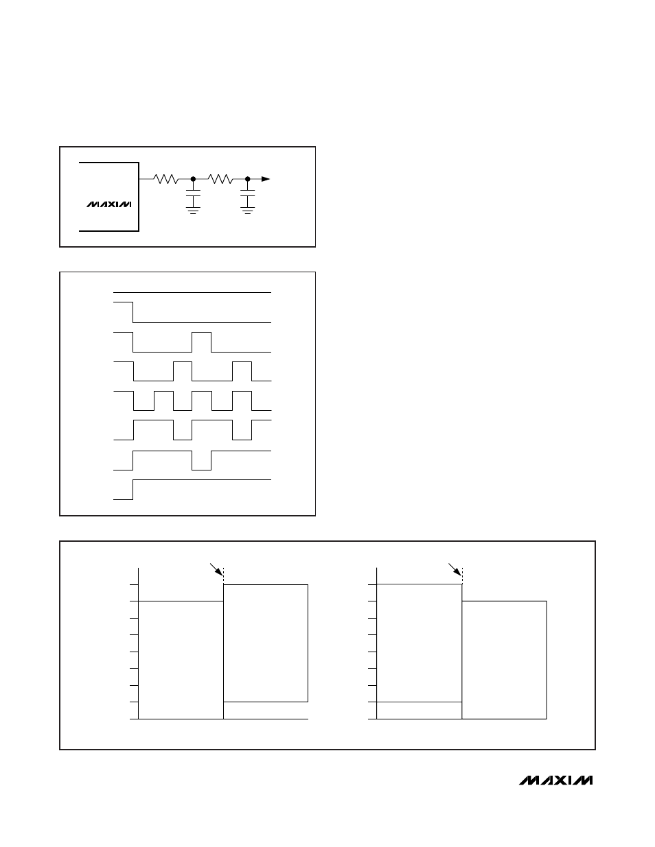
using pulse-density modulation. It provides much lower
output ripple than a standard digital PWM output given
the same clock rate and filter components. Before t
INIT
,
the DAC1 and DAC2 outputs are high impedance.
The external RC filter components are chosen based
on ripple requirements, output load, delta-sigma fre-
quency, and desired response time. A recommended
filter is shown in Figure 9.
The DS1874’s delta-sigma outputs are 9 bits. For illus-
trative purposes, a 3-bit example is provided. Each
possible output of this 3-bit delta-sigma DAC is given in
Figure 10.
In LUT mode, DAC1 and DAC2 are each controlled by a
separate 8-bit, 4°C-resolution, temperature-addressed
LUT. The delta-sigma outputs use a 9-bit structure. The
8-bit LUTs are either loaded directly into the MSBs (8:1)
or the LSBs (7:0). This is determined by DAC1TI (Table
02h, Register C3h), DAC2TI (Table 02h, Register C4h),
DAC1TC (Table 02h, Register C6h, bit 6), and DAC2TC
(Table 02h, Register C6h, bit 5). See Figure 11 for more
details. The DAC1 LUT (Table 07h) and DAC2 LUT
(Table 08h) are nonvolatile and password-2 protected.
The reference input, REFIN, is the supply voltage for
the output buffer of DAC1 and DAC2. The voltage con-
nected to REFIN must be able to support the edge rate
requirements of the delta-sigma outputs. In a typical
application, a 0.1µF capacitor should be connected
between REFIN and ground.
20
______________________________________________________________________________________
LUT LOADED TO [7:0]
LUT LOADED TO [7:0]
DAC[1/2]TI
8
7
6
5
4
3
2
1
0
DAC[1/2]TI
DAC[1/2]TC = 0
TEMPERATURE (
°C)
-40
+102
TEMPERATURE (
°C)
-40
+102
DAC[1/2]TC = 1
LUT LOADED TO [8:1]
(DAC BIT 0 = 0)
LUT LOADED TO [8:1]
(DAC BIT 0 = 0)
DELTA-SIGMA DACA OR DACB
8
7
6
5
4
3
2
1
0
DELTA-SIGMA DACA OR DACB
Figure 11. DAC1/DAC2 LUT Assignments
DS1874
DAC1/DAC2
3.24k
Ω
3.24k
Ω
0.01
μF
0.01
μF
OUTPUT
SFP+ Controller with Digital LDD Interface
1
2
3
4
5
6
7
0
Figure 10. Delta-Sigma Outputs
Figure 9. Recommended RC Filter for DAC1/DAC2