Pin description, Ds1874 sfp+ controller with digital ldd interface – Rainbow Electronics DS1874 User Manual
Page 10
DS1874
SFP+ Controller with Digital LDD Interface
10
______________________________________________________________________________________
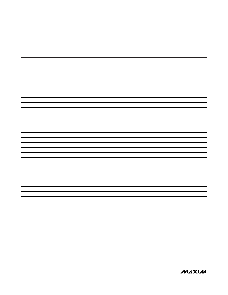
Pin Description
PIN
NAME
FUNCTION
1
RSELOUT
Rate-Select Output
2 SCL
I
2
C Serial-Clock Input
3 SDA
I
2
C Serial-Data Input/Output
4
TXF
Transmit-Fault Input and Output. The output is open drain.
5 LOS
Loss-of-Signal
Input
6
IN1
Digital Input. General-purpose input with AS1 in SFF-8079 or RS1 in SFF-8431.
7 TXD
Transmit-Disable
Input
8, 17, 21
GND
Ground Connection
9 RSEL
Rate-Select
Input
10
TXDOUT
Transmit-Disable Output
11
MON4
External Monitor Input 4
12, 13
MON3P,
MON3N
Differential External Monitor Input 3 and LOS Quick Trip
14
MON1
External Monitor Input 1 and HBATH Quick Trip
15, 23
V
CC
Power-Supply
Input
16
MON2
External Monitor Input 2. Feedback voltage for APC loop and HTXP/LTXP quick trip.
18
REFIN
Reference Input for DAC1 and DAC2
19, 20
DAC1, DAC2 Delta-Sigma Output 1/2
22 N.C.
No
Connection
24 CSELOUT
Chip-Select Output. Part of the 3-wire interface to the MAX3798/MAX3799 laser driver/limiting
amplifier.
25 SCLOUT
Serial-Clock Output. Part of the 3-wire interface to the MAX3798/MAX3799 laser driver/limiting
amplifier.
26 SDAOUT
Serial-Data Input/Output. Part of the 3-wire interface to the MAX3798/MAX3799 laser driver/limiting
amplifier.
27
LOSOUT
Open-Drain Receive Loss-of-Signal Output
28
OUT1
Digital Output. General-purpose output with AS1 output in SFF-8079 or RS1 output in SFF-8431.
— EP
Exposed
Pad