Wire interface timing, Ds1874 and max3798/max3799 c, Normal operation – Rainbow Electronics DS1874 User Manual
Page 23: Manual operation, Ds1874 and max3798/max3799 communication, Figure 15. 3-wire timing, Ds1874 sfp+ controller with digital ldd interface
after the CSELOUT has been set to 1. Each operation
consists of 16-bit transfers (15-bit address/data, 1-bit
RWN). All data transfers are MSB first.
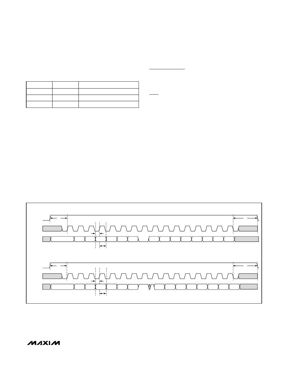
Write Mode (RWN = 0): The master generates 16 clock
cycles at SCLOUT in total. It outputs 16 bits (MSB first)
to the SDAOUT line at the falling edge of the clock. The
master closes the transmission by setting the
CSELOUT to 0.
Read Mode (RWN = 1): The master generates 16 clock
cycles at SCLOUT in total. It outputs 8 bits (MSB first)
to the SDAOUT line at the falling edge of the clock. The
SDAOUT line is released after the RWN bit has been
transmitted. The slave outputs 8 bits of data (MSB first)
at the rising edge of the clock. The master samples
SDAOUT at the falling edge of SCLOUT. The master
closes the transmission by setting the CSELOUT to 0.
3-Wire Interface Timing
Figure 15 shows the 3-wire interface timing. Figure 16
shows the 3-wire state machine. See the
3-Wire Digital
Interface Specification
table for more information.
DS1874 and MAX3798/MAX3799
Communication
Normal Operation
The majority of the communication between the two
devices consists of bias adjustments for the APC loop.
After each temperature conversion, the laser modula-
tion setting must be updated. Status registers TXSTAT1
and TXSTAT2 are read between temperature updates
at a regular interval: t
RR
(see the
Electrical Characteristics
table). The results are stored in TXSTAT1 and TXSTAT2
(Table 02h, F4h–F5h).
Manual Operation
The MAX3798/MAX3799 are manually controllable
using four registers in the DS1874: 3WCTRL,
ADDRESS, WRITE, and READ. Commands can be
manually issued while the DS1874 is in normal opera-
tion mode. It is also possible to suspend normal 3-wire
commands so that only manual operation commands
are sent (3WCTRL, Table 02h, Register F8h).
DS1874
SFP+ Controller with Digital LDD Interface
______________________________________________________________________________________
23
BIT
NAME
DESCRIPTION
15:9
Address
7-bit internal register address
8
RWN
0: write; 1: read
7:0
Data
8-bit read or write data
CSELOUT
SCLOUT
SDAOUT
CSELOUT
SCLOUT
SDAOUT
1
2
3
4
5
6
7
8
A6
9
10
11
12
13
14
15
0
1
2
3
4
5
6
7
8
9
10
11
12
13
14
15
0
A5
A4
A3
A2
A1
RWN
D7
D6
D5
D4
D3
D2
D1
D0
D7
D6
D5
D4
D3
D2
D1
D0
RWN
WRITE MODE
READ MODE
A0
A6
A5
A4
A3
A2
A1
A0
t
L
t
L
t
DS
t
DH
t
DS
t
DH
t
T
t
T
Figure 15. 3-Wire Timing