Ds1874 sfp+ controller with digital ldd interface – Rainbow Electronics DS1874 User Manual
Page 70
DS1874
SFP+ Controller with Digital LDD Interface
70
______________________________________________________________________________________
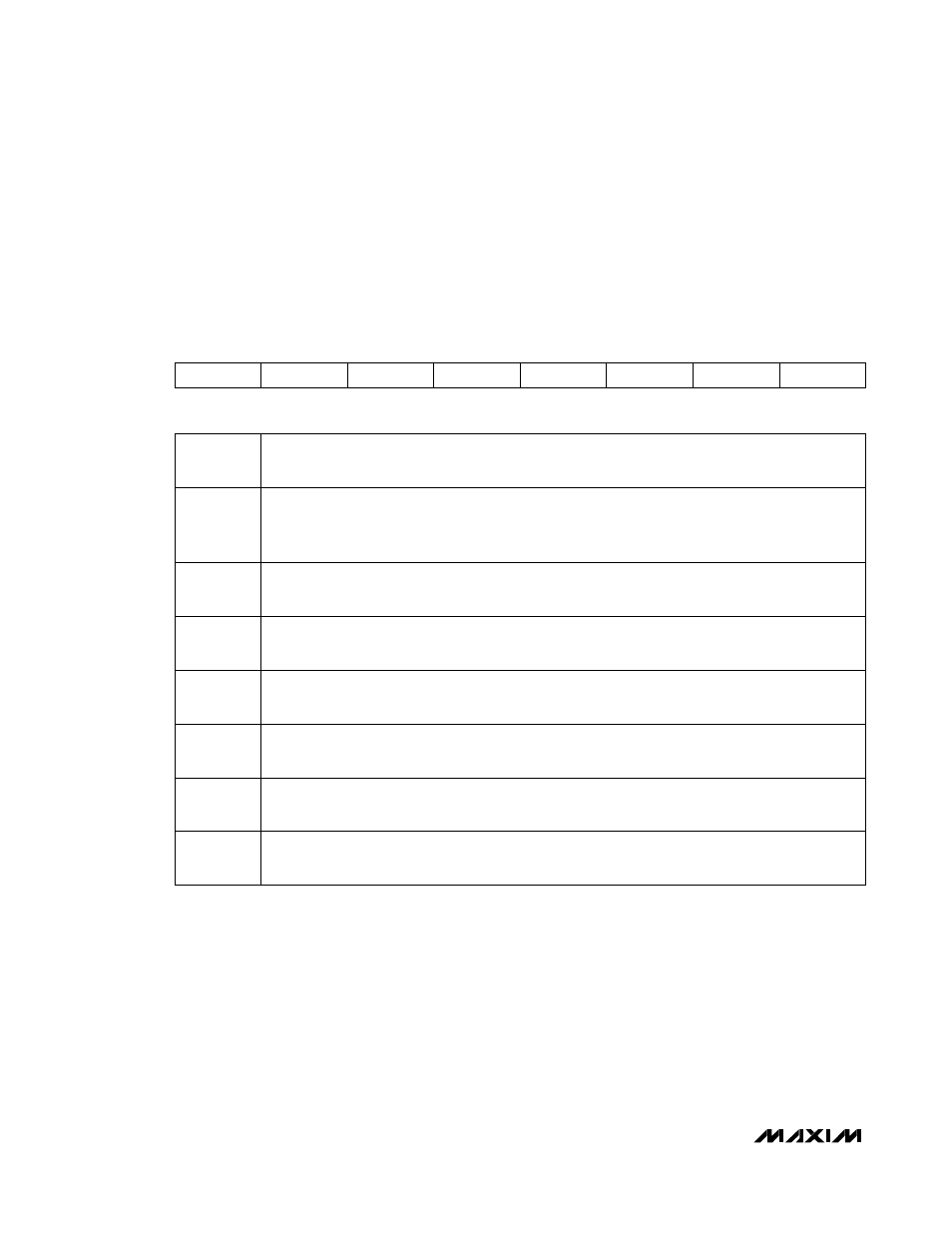
Table 02h, Register C0h: PW_ENA
FACTORY
DEFAULT
10h
READ ACCESS
PW2 or (PW1 and RWTBL246) or (PW1 and RTBL246)
WRITE ACCESS
PW2 or (PW1 and RWTBL246)
MEMORY TYPE
Nonvolatile (SEE)
C0h RWTBL78
RWTBL1C RWTBL2
RWTBL1A
RWTBL1B
WLOWER
WAUXA
WAUXB
BIT
7
BIT
0
BIT
7
RWTBL78: Tables 07h–08h
0 = (Default) Read and write access for PW2 only.
1 = Read and write access for both PW1 and PW2.
BIT
6
RWTBL1C: Table 01h or 05h bytes F8h–FFh. Table address is dependent on MASK bit (Table 02h,
Register 89h).
0 = (Default) Read and write access for PW2 only.
1 = Read and write access for both PW1 and PW2.
BIT
5
RWTBL2: Tables 02h, except for PW1 value locations (Table 02h, Registers B0h–B3h).
0 = (Default) Read and write access for PW2 only.
1 = Read and write access for both PW1 and PW2.
BIT
4
RWTBL1A: Read and Write Table 01h, Registers 80h–BFh
0 = Read and write access for PW2 only.
1 = (Default) Read and write access for both PW1 and PW2.
BIT
3
RWTBL1B: Read and Write Table 01h, Registers C0h–F7h
0 = (Default) Read and write access for PW2 only.
1 = Read and write access for both PW1 and PW2.
BIT
2
WLOWER: Write Lower Memory Bytes 00h–5Fh in main memory. All users can read this area.
0 = (Default) Write access for PW2 only.
1 = Write access for both PW1 and PW2.
BIT
1
WAUXA: Write Auxiliary Memory, Registers 00h–7Fh. All users can read this area.
0 = (Default) Read and write access for PW2 only.
1 = Write access for both PW1 and PW2.
BIT
0
WAUXB: Write Auxiliary Memory, Registers 80h–FFh. All users can read this area.
0 = (Default) Read and write access for PW2 only.
1 = Write access for both PW1 and PW2.