Ds1874 sfp+ controller with digital ldd interface – Rainbow Electronics DS1874 User Manual
Page 82
DS1874
SFP+ Controller with Digital LDD Interface
82
______________________________________________________________________________________
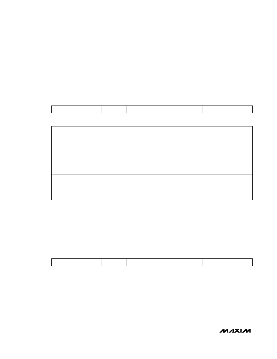
Table 02h, Register F8h: 3WCTRL
FACTORY
DEFAULT
00h
READ ACCESS
PW2 or (PW1 and RWTBL246) or (PW1 and RTBL246)
WRITE ACCESS
PW2 or (PW1 and RWTBL246)
MEMORY
TYPE
Volatile
F8h RESERVED RESERVED RESERVED RESERVED RESERVED RESERVED
3WRW
3WDIS
BIT
7
BIT
0
BITS
7:2
RESERVED
BIT
1
3WRW: Initiates a 3-wire write or read operation. The write command uses the memory address
found in the 3-wire ADDRESS register (Table 02h, Register F9h) and the data from the 3-wire WRITE
register (Table 02h, Register FAh). This bit clears itself at the completion of the write operation.
The read command uses the memory address found in the 3-wire ADDRESS register (Table 02h,
Register F9h). The address determines whether a read or write operation is to be performed. This
bit clears itself at the completion of the read operation.
0 = (Default) Reads back as 0 when the write or read operation is completed.
1 = Initiates a 3-wire write or read operation.
BIT
0
3WDIS: Disables all automatic communication across the 3-wire interface. This includes all
updates from the LUTs, APC loop, and status registers. The only 3-wire communication is with the
manual mode of operation.
0 = (Default) Automatic communication is enabled.
1 = Disables automatic communication.
FACTORY
DEFAULT
00h
READ ACCESS
PW2 or (PW1 and RWTBL246) or (PW1 and RTBL246)
WRITE ACCESS
PW2 or (PW1 and RWTBL246)
MEMORY
TYPE Volatile
F9h 2
7
2
6
2
5
2
4
2
3
2
2
2
1
2
0
BIT
7
BIT
0
This byte is used during manual 3-wire communication. When a manual read or write is initiated, this register
contains the address for the operation.
Table 02h, Register F9h: ADDRESS