Ds1874 sfp+ controller with digital ldd interface – Rainbow Electronics DS1874 User Manual
Page 65
DS1874
SFP+ Controller with Digital LDD Interface
______________________________________________________________________________________
65
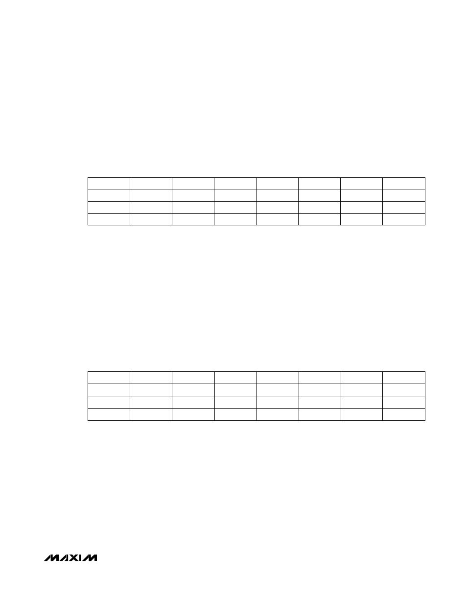
Table 02h, Register B0h–B3h: PW1
FACTORY
DEFAULT
FFFF
FFFFh
READ
ACCESS N/A
WRITE ACCESS
PW2 or (PW1 and WPW1)
MEMORY TYPE
Nonvolatile (SEE)
B0h 2
31
2
30
2
29
2
28
2
27
2
26
2
25
2
24
B1h 2
23
2
22
2
21
2
20
2
19
2
18
2
17
2
16
B2h 2
15
2
14
2
13
2
12
2
11
2
10
2
9
2
8
B3h 2
7
2
6
2
5
2
4
2
3
2
2
2
1
2
0
BIT
7
BIT
0
The PWE value is compared against the value written to this location to enable PW1 access. At power-on, the
PWE value is set to all ones. Thus, writing these bytes to all ones grants PW1 access on power-on without
writing the password entry. All reads of this register are 00h.
FACTORY DEFAULT
FFFF FFFFh
READ
ACCESS N/A
WRITE
ACCESS
PW2
MEMORY TYPE
Nonvolatile (SEE)
B4h 2
31
2
30
2
29
2
28
2
27
2
26
2
25
2
24
B5h 2
23
2
22
2
21
2
20
2
19
2
18
2
17
2
16
B6h 2
15
2
14
2
13
2
12
2
11
2
10
2
9
2
8
B7h 2
7
2
6
2
5
2
4
2
3
2
2
2
1
2
0
BIT
7
BIT
0
The PWE value is compared against the value written to this location to enable PW2 access. At power-on, the PWE
value is set to all ones. Thus, writing these bytes to all ones grants PW2 access on power-on without writing the
password entry. All reads of this register are 00h.
Table 02h, Register B4h–B7h: PW2