Shadowed eeprom, Figure 19. memory map, Ds1874 sfp+ controller with digital ldd interface – Rainbow Electronics DS1874 User Manual
Page 29: Register descriptions
DS1874
SFP+ Controller with Digital LDD Interface
______________________________________________________________________________________
29
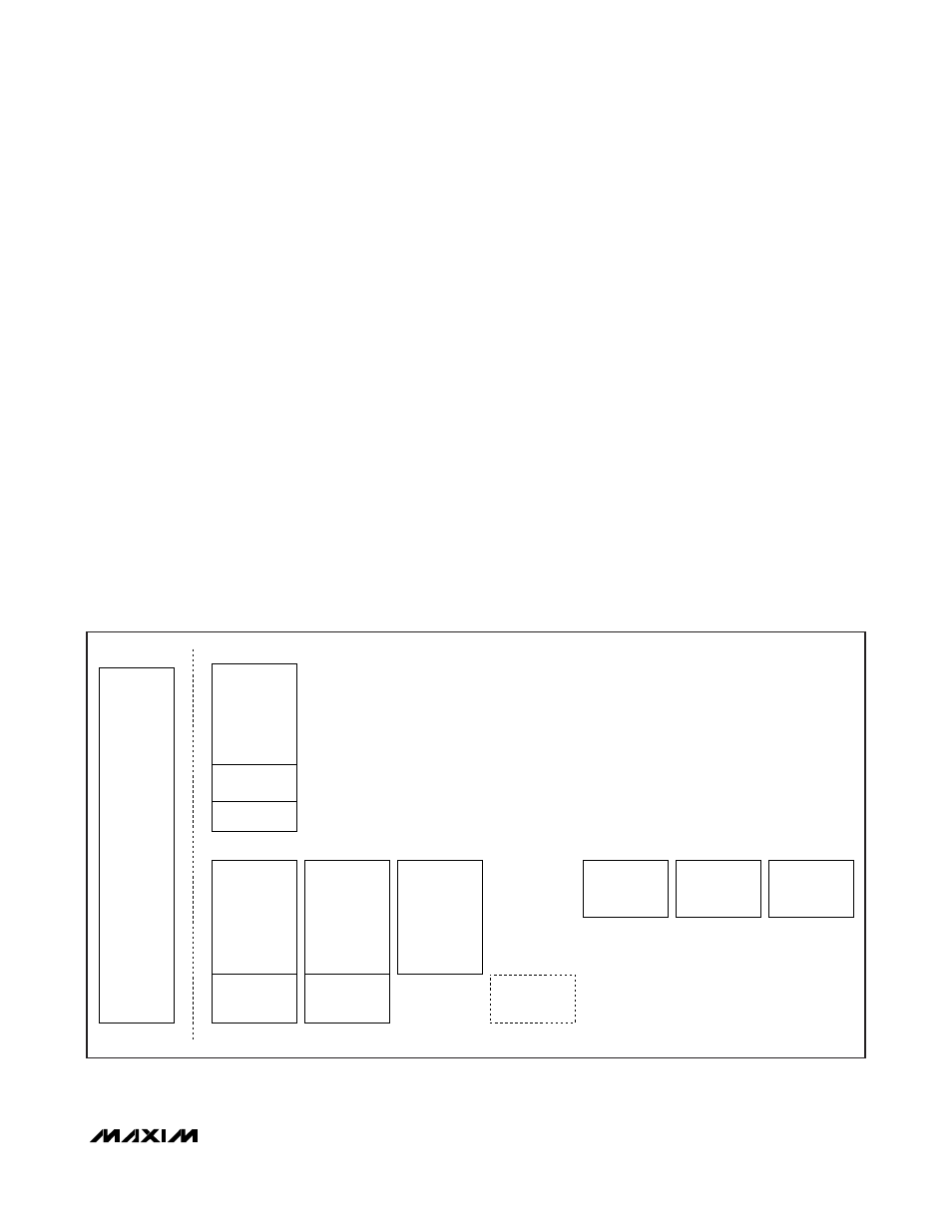
Table 05h is empty by default. It can be configured to
contain the alarm- and warning-enable bytes from Table
01h, Registers F8h–FFh with the MASK bit enabled
(Table 02h, Register 89h). In this case Table 01h is
empty.
Table 06h contains a temperature-indexed LUT that
allows the APC set point to change as a function of
temperature to compensate for tracking error (TE). The
APC LUT has 36 entries that determine the APC setting
in 4°C windows between -40°C and +100°C.
Table 07h contains a temperature-indexed LUT for con-
trol of DAC1. The LUT has 36 entries that determine the
DAC setting in 4°C windows between -40°C and +100°C.
Table 08h contains a temperature-indexed LUT for con-
trol of DAC2. The LUT has 36 entries that determine the
DAC setting in 4°C windows between -40°C and +100°C.
Auxiliary Memory (device A0h) contains 256 bytes of
EE memory accessible from address 00h–FFh. It is
selected with the device address of A0h.
See the
Register Descriptions
section for more com-
plete details of each byte’s function, as well as for
read/write permissions for each byte.
Shadowed EEPROM
Many NV memory locations (listed within the
Register
Descriptions
section) are actually shadowed EEPROM
that are controlled by the SEEB bit in Table 02h,
Register 80h.
The DS1874 incorporates shadowed-EEPROM memory
locations for key memory addresses that can be written
many times. By default the shadowed-EEPROM bit,
SEEB, is not set and these locations act as ordinary
EEPROM. By setting SEEB, these locations function like
SRAM cells, which allow an infinite number of write
cycles without concern of wearing out the EEPROM.
Setting SEEB also eliminates the requirement for the
EEPROM write time, t
WR
. Because changes made with
SEEB enabled do not affect the EEPROM, these
changes are not retained through power cycles. The
power-on value is the last value written with SEEB dis-
abled. This function can be used to limit the number of
EEPROM writes during calibration or to change the
monitor thresholds periodically during normal operation
helping to reduce the number of times EEPROM is writ-
ten. Figure 19 indicates which locations are shadowed
EEPROM.
EEPROM
(256 BYTES)
FFh
I
2
C ADDRESS A0h
AUXILIAR
Y DEVICE
MAIN DEVICE
00h
ALARM-
ENABLE ROW
(8 BYTES)
PASSWORD ENTRY
(PWE) (4 BYTES)
TABLE-SELECT
BYTE
FFh
80h
F8h
TABLE 01h
EEPROM
(120 BYTES)
F7h
7Fh
00h
LOWER
MEMORY
3W CONFIG
FFh
80h
F8h
TABLE 02h
NONLOOKUP
TABLE CONTROL
AND
CONFIGURATION
REGISTERS
E7h
80h
TABLE 04h
MOD
LOOKUP TABLE
(72 BYTES)
C7h
F8h
TABLE 05h
ALARM-ENABLE ROW
(8 BYTES) FFh
80h TABLE 06h
TRACKING ERROR
LOOKUP TABLE
(36 BYTES) A3h
80h
TABLE 07h
DAC1 LUT
A3h
80h
TABLE 08h
DAC2 LUT
A3h
NOTE 1: IF ASEL = 0, THEN THE MAIN DEVICE I
2
C SLAVE ADDRESS IS A2h.
IF ASEL = 1, THEN THE MAIN DEVICE I
2
C SLAVE ADDRESS IS DETERMINED BY THE VALUE IN
TABLE 02h, REGISTER 8Ch.
NOTE 2: TABLE 00h DOES NOT EXIST.
NOTE 3: ALARM-ENABLE ROW CAN BE CONFIGURED TO EXIST AT TABLE 01h OR TABLE 05h USING THE
MASK BIT IN TABLE 02h, REGISTER 89h.
Figure 19. Memory Map